When Should You Specify a 2-Layer, 30mil TMM10i Board for Your Next Project?


In the complex world of PCB design, material and configuration selection is a critical decision that can make or break your project's performance, cost, and timeline. While a vast array of options exists, knowing the precise application for a specialized board like the 2-Layer, 30mil TMM10i PCB with Immersion Tin finish is key to leveraging its full potential.


This isn't a one-size-fits-all solution; it's a precision instrument. Specifying it at the right time ensures optimal performance, reliability, and cost-efficiency. You should seriously consider this specific PCB configuration in the following scenarios:


1. When Your Application Operates at High Frequencies (RF & Microwave)

This is the most compelling reason to choose this board. The Rogers TMM10i material is engineered specifically for high-frequency performance.


  • Stable Dielectric Constant (Dk of 9.80±0.245): A high and stable Dk allows for the design of smaller wavelength circuits. This means you can create more compact filters, antennas, and couplers without sacrificing electrical performance. The low tolerance ensures your design behaves predictably in production, batch after batch.
  • Low Dissipation Factor (0.0020 @ 10 GHz): At microwave frequencies, signal loss is a major concern. The low loss tangent of TMM10i ensures minimal signal attenuation, which is critical for maintaining efficiency in power amplifiers, signal integrity in transceivers, and sensitivity in receiving systems.
  • Specify this board for: Power amplifiers, low-noise amplifiers (LNAs), filters, couplers, and oscillators operating in the GHz range.


2. When You Require Superior Thermal and Mechanical Stability

Environmental robustness is non-negotiable in many fields. The TMM10i substrate excels where temperature fluctuations and mechanical stress are a concern.


  • CTE Matched to Copper: The Coefficient of Thermal Expansion (CTE) of TMM10i (19/19/20 ppm/°C) is closely matched to the copper foil (~17 ppm/°C). This is crucial for reliability. During thermal cycling (e.g., power on/off or environmental changes), the board and the copper traces expand and contract at nearly the same rate. This drastically reduces the risk of plated through-hole (PTH) barrel cracking, trace delamination, and long-term failure.
  • High Decomposition Temperature (Td 425°C): This allows the board to withstand the high temperatures of lead-free solder assembly processes without degrading, ensuring manufacturing yield and long-term reliability.
  • Resists Creep and Cold Flow: The thermoset composite structure maintains its dimensional stability under continuous mechanical stress, preventing deformation that could alter electrical characteristics.
  • Specify this board for: Automotive radar, satellite communication systems, aerospace electronics, and any application destined for harsh environments.


3. When Your Design Relies on Reliable Plated Through-Holes (PTHs) and Vias

The product description explicitly mentions TMM10i is "designed for high plated thru-hole reliability." This is a foundational feature.


  • Robust Via Construction: With a via plating thickness of 20µm and a material that bonds well with copper, the PTHs in this board are exceptionally robust. The 30mil (0.762mm) core thickness is manageable for a 2-layer board, ensuring a reliable plating process throughout the hole barrel.
  • No Special Pre-Treatment Required: Unlike pure PTFE materials, TMM10i does not require a sodium napthanate treatment prior to electroless copper plating. This simplifies the fabrication process, reduces potential failure points, and improves overall PTH quality and consistency.
  • Specify this board for: Dense interconnects, power grounds, and any design where the integrity of the connection between layers is paramount to the function and lifespan of the product.


4. When You Need a Planar Surface for Fine-Pitch Components or Wire Bonding

The Immersion Tin (ImSn) surface finish is a strategic choice for specific assembly needs.


  • Flat, Planar Surface: Immersion tin provides a very flat surface, which is ideal for the fine-pitch components commonly found in RF circuits. It eliminates the "coplanarity" issues that can arise with HASL (Hot Air Solder Leveling) finishes.
  • Excellent for Wire Bonding: The thermoset resin base of TMM10i provides a stable, non-porous surface that is highly reliable for both gold and aluminum wire bonding, a critical assembly process in many high-performance RF and microwave multi-chip modules.
  • Specify this board for: Designs using fine-pitch BGA or QFN packages, modules requiring wire bonding, or any application where a perfectly flat soldering surface is critical.


5. When Your Circuit Complexity is Managed on Two Layers

A 2-layer design is often sufficient for many RF functional blocks like filters, amplifiers, or antenna feed networks. Using this TMM10i configuration in such cases is a model of cost-effective performance.


  • Simplified Fabrication: A 2-layer board is less complex to manufacture than a multilayer one, leading to higher fabrication yields, shorter lead times, and lower costs.
  • Optimized Stackup: The symmetric stackup (1oz Cu - 30mil TMM10i core - 1oz Cu) provides a consistent environment for controlled impedance lines on both layers, which is perfectly adequate for many microstrip and stripline-inspired designs.
  • Ideal for Dedicated RF Modules: The provided PCB Statistics (e.g., 10 components, 15 vias, 2 nets) suggest this board is perfect for a specific, critical function within a larger system.
  • Specify this board for: Individual RF sub-assemblies, patch antenna arrays, sensor modules, and other applications where the circuit complexity does not necessitate four or more layers.
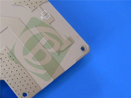


TMM10i PCB 2-layer 30mil Immersion Tin


When to Look for an Alternative

Conversely, you should consider a different PCB specification if your project has:


  • High-Density Digital Logic: Requires 4 or more layers for power integrity and complex routing.
  • Extreme Heat Dissipation Needs: While stable, TMM10i's thermal conductivity (0.76 W/m/K) may be lower than specialized metal-core or alumina substrates for high-power applications.
  • A Need for On-Board Shielding: This requires dedicated ground planes or buried layers, which a 4+ layer board would provide.
  • A Strict Budget for Consumer-Grade Electronics: TMM10i is a performance-grade material; for non-critical, low-frequency applications, standard FR-4 is far more economical.


Conclusion: Making the Strategic Choice

Specifying the 2-Layer, 30mil TMM10i high frequency PCB with Immersion Tin is a strategic decision for engineers and designers who need a reliable, high-performance substrate for demanding high-frequency and thermal applications. It is the ideal choice when your priorities are signal integrity at microwave frequencies, robust plated through-holes, exceptional thermal stability, and a reliable surface for assembly.


By understanding the unique synergy between the TMM10i material, the 30mil thickness, and the immersion tin finish, you can select this board for your next RF power amplifier, satellite communication module, or advanced radar system, ensuring it is built on a foundation of proven performance and reliability.
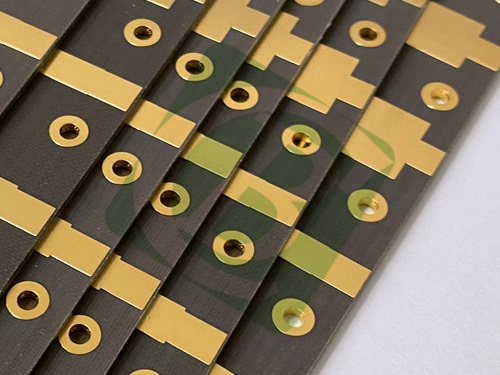


Why Choose a Silver/Gold Surface Finish for High-Frequency PCBs?


In the world of high-frequency and radio frequency (RF) PCB design, every decision impacts performance. From the laminate material to the trace geometry, engineers labor over details to minimize loss and preserve signal integrity. One of the most critical choices lies in the surface finish—the final coating applied to the exposed copper circuitry. While options like ENIG (Electroless Nickel Immersion Gold) and HASL (Hot Air Solder Leveling) are common, for demanding applications, the silver/gold plate (gold over silver) finish stands out as a superior solution.


Here’s a breakdown of why this specific finish is the go-to choice for high-performance PCBs, such as our TLY-3 2-layer 20mil board.


TLY-3 PCB 2-layer 20mil Silver Gold


1. The Unmatched Electrical Performance of Silver

At high frequencies, especially into the millimeter-wave range (like 24 GHz, 77 GHz, and beyond), the "skin effect" becomes dominant. This phenomenon causes the electrical current to flow primarily on the outer surface of the conductor. Therefore, the properties of the surface finish itself directly influence the signal's insertion loss.


  • High Conductivity: Pure silver is the most electrically conductive metal, even slightly better than copper. When used as a base plating layer, it creates an exceptionally low-loss path for RF signals. Compared to a standard ENIG finish, which uses a less-conductive nickel barrier layer, silver plating offers significantly lower signal loss at high frequencies.


  • Smooth Surface Profile: The electroplating process for silver results in a very flat and uniform surface. This smoothness is crucial for consistent impedance control in delicate transmission lines like microstrips or coplanar waveguides, where surface roughness can increase loss and scatter signals.


2. The Protective and Reliable Role of Gold

While silver is an excellent conductor, it has a major Achilles' heel: it tarnishes and oxidizes easily when exposed to sulfur in the atmosphere. This oxidation layer is non-conductive and would severely degrade performance over time. This is where the thin layer of gold comes in.


  • Inert Protection: Gold is a noble metal, meaning it does not oxidize or corrode in normal environments. The thin, immersion gold layer hermetically seals the underlying silver, protecting it from the elements and ensuring long-term shelf life and reliability. 
  • Excellent Contact Properties: For PCBs designed to be plugged into a connector or make direct contact with a metal housing (e.g., in an antenna module), gold is ideal. It provides a stable, low-resistance contact interface that won't degrade through repeated mating cycles.


3. The Synergy of the Duo: Best of Both Worlds

The "gold over silver" finish is a classic case of a perfect partnership. Each metal plays a distinct role:


  • Silver serves as the workhorse conductor, providing the ultimate electrical performance.
  • Gold acts as the protective shield, guaranteeing long-term solderability, stable contact resistance, and reliability.
  • This combination delivers a surface that is both electrically superior at high frequencies and robust enough for demanding automotive, aerospace, and telecommunications applications.


Comparison to Other Common Finishes

To fully appreciate the silver/gold finish, it helps to compare it to alternatives:


  • vs. ENIG (Electroless Nickel Immersion Gold): ENIG is popular but problematic for very high frequencies. The nickel layer, while preventing copper diffusion, has poor conductivity and introduces magnetic losses, which are detrimental above a few GHz. Silver/gold avoids this lossy nickel layer entirely.
  • vs. Immersion Silver: Immersion silver alone is a good option but is more susceptible to tarnishing and has a shorter shelf life than the gold-protected version.
  • vs. OSP (Organic Solderability Preservative): OSP is a thin, organic layer that offers little to no protection for exposed contacts and can be unsuitable for certain assembly processes.


Conclusion: A Finish for Mission-Critical Applications

Choosing a silver/gold surface finish is not about luxury; it's a calculated engineering decision for applications where signal integrity and long-term reliability are non-negotiable. For our TLY-3 PCB  20mil Silver Gold board, this finish is the perfect complement to the high-frequency properties of the TLY-3 laminate. It ensures that the exceptional signal performance designed into the board is not compromised at the surface level, making it the ideal choice for:


  • 77 GHz Automotive Radar Sensors
  • Satellite Communication Phased Arrays
  • Millimeter-Wave Antennas (Ka, E, W-Band)


When your design cannot afford unnecessary losses, the silver/gold finish PCB provides the electrical edge and enduring protection you need.


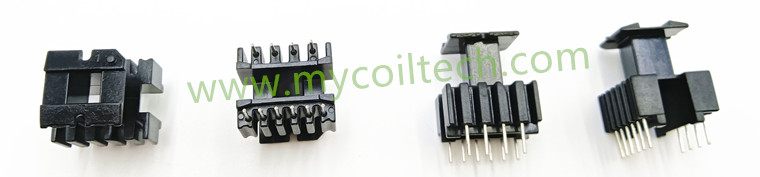
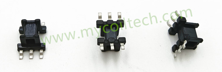
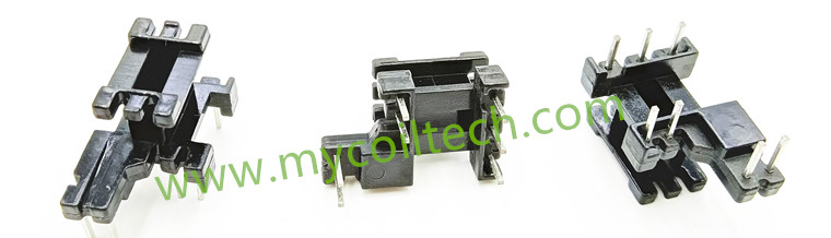
EE-Type Bobbin

1. Structural Features

The ferrite magnetic core of an EE-Type Bobbin is shaped like two symmetrical "E" letters combined, with the width of the central leg usually equal to that of the two side legs. This symmetrical structural design ensures a more uniform magnetic field distribution when winding the coil, which helps enhance the performance of the transformer. The pins of the EE-Type Bobbin are distributed on both sides of the bobbin, and their quantity and spacing vary according to different models and application requirements. Common sizes include EE5, EE8, EE13, EE19, etc. EE-Type Bobbins of different sizes are suitable for transformers of different power levels. For example, EE5 is used for low-power transformers and often applied in auxiliary power supplies for small electronic devices, while EE19 can be used in higher-power industrial power transformers.

Common mode choke for converter

2. Application Scenarios

EE-Type Bobbins are widely used in various types of transformers, including low-frequency transformers and high-frequency transformers. In the low-frequency field (e.g., power-frequency transformers), EE-Type Bobbins are often used in power transmission and distribution systems to convert high voltage into low voltage suitable for household and industrial use. In the high-frequency field (e.g., EE19 switching power supply transformers), EE-Type Bobbins can achieve efficient electrical energy conversion under high-frequency operating conditions, providing stable power for electronic devices. Additionally, EE-Type Bobbins are also applied in fields such as audio transformers and pulse transformers to meet the performance requirements of transformers in different applications.

Customized EMI filter for AC&DC line

3. Performance Advantages

The symmetrical structure of the EE-Type Bobbin results in uniform magnetic field distribution and low leakage inductance, which can improve the efficiency and power factor of the transformer. Therefore, it is also widely used in bobbins for EE05 LED driver transformer bobbin. Meanwhile, due to its simple structure, relatively mature manufacturing process, and low cost, it has high cost-effectiveness in the market. Besides, EE-Type Bobbins have high versatility—products with various sizes and pin configurations are easily available, which facilitates engineers' design and application work.

CMC choke for Converter factory


4.Contact us today to explore bulk orders or request technical specifications.

Email: sales008@mycoiltech.com

Whats app ID: +86 18788862885

Name:Alex~Mycoiltech


In the world of wearable technology, the Q520 Smart Ring stands out by proving that meaningful health insights don't require bulky devices. Weighing just 4.2 grams with a slim 2.1mm profile, this elegantly designed ring disappears on your finger while working quietly in the background to monitor your wellbeing. Crafted from medical-grade alloy using advanced vacuum plating technology, it combines durability with a sophisticated look that transitions seamlessly from workout sessions to formal occasions.


What makes the Q520 particularly valuable is its comprehensive approach to health tracking. The ring continuously monitors your heart rhythm, blood oxygen levels, and sleep patterns, providing gentle insights into your daily health trends. Unlike smartwatches that require frequent charging, the Q520 delivers up to six days of use on a single charge, and its 5ATM water resistance means you never need to remove it for showers or swimming. The automatic activity recognition tracks exercises like running and cycling, while the companion app presents your data in clear, understandable formats.


For those seeking a discreet health companion that fits effortlessly into their lifestyle, the Q520 offers the perfect solution. It provides the essential health monitoring most people need, without the complexity or conspicuousness of larger devices, making health awareness a natural part of your daily routine.

Bulk Wholesale Smart Watches for Retail

The T5 Smart Watch brings a new level of health awareness to your daily life through its thoughtful features and elegant design. Centered around a beautiful 1.43-inch AMOLED display that stays always visible, this watch keeps your important health information readily available without being overwhelming.


What makes the T5 special is its practical approach to health monitoring. The heart health feature lets you check your heart rhythm anytime, providing helpful insights about your cardiovascular status. The 30-second health check gives you a quick overview of your stress levels and body temperature, while the blood sugar trends feature helps you understand how your levels change throughout the day. For those keeping an eye on their metabolic health, the watch also tracks indicators like uric acid and lipids.


The T5 quietly works in the background, monitoring your heart rate, blood oxygen, sleep patterns, and blood pressure around the clock. With water-resistant construction and comfortable design, it fits seamlessly into your daily routine - whether you're working, exercising, or resting. For anyone looking to stay more connected to their wellbeing, the T5 offers gentle guidance and useful insights in a package that feels both sophisticated and approachable.

IP68 waterproof AMOLED wearable

In the realm of modern telecommunications infrastructure maintenance and deployment, two essential tools play vital roles in distinct yet interconnected functions—Radio Communication Vans and Fusion Splicers. Both are central to ensuring efficient, reliable, and seamless operation of communication networks, each with its unique capabilities that contribute to the overall functionality and resilience of the infrastructure.


Radio Communication Vans, also known as Mobile Communications Units, are versatile vehicles equipped with advanced radio communication equipment to facilitate seamless and reliable wireless communication in diverse scenarios. These vans serve as mobile command centers capable of establishing communication links in emergency situations, remote locations, events, or areas with limited existing infrastructure.


Equipped with a range of communication technologies such as radios, antennas, satellite dishes, and power supplies, Radio Communication Vans provide critical communication services for public safety, disaster response, broadcasting, event management, and various other applications. These vans act as mobile hubs that enable communication between field personnel, command centers, and other relevant stakeholders, ensuring coordination, information dissemination, and connectivity in challenging environments.


Fusion Splicers are essential tools used in the installation and maintenance of fiber optical networks. These devices enable technicians to create permanent, low-loss connections between optical fibers by fusing the fiber ends together. By precisely aligning and melting the fibers, fusion splicers ensure efficient light transmission across the network, minimizing signal loss and maximizing network performance.


Fusion splicing plays a critical role in expanding and upgrading fiber optic infrastructures by enabling the seamless connection of optical fibers, creating a robust network that can meet the demands of high-speed data transmission and telecommunications services. These splicers are indispensable in maintaining network integrity, reducing signal attenuation, and minimizing service disruptions in fiber optic communication networks.


The relationship between Radio Communication Vans and Fusion Splicers becomes apparent in scenarios where the installation and maintenance of fiber optic communication links are required in remote, temporary, or challenging environments. In such situations, Radio Communication Vans provide the necessary infrastructure for on-site operations, serving as a mobile base for technicians to deploy and coordinate their activities.


Fusion Splicers, on the other hand, play a crucial role in establishing high-quality fiber optic connections that enable reliable data transmission through the network. Technicians working from Radio Communication Vans can use Fusion Splicers to create durable and low-loss fiber optic splices, ensuring seamless connectivity and optimal performance of the communication links.


In conclusion, the collaboration between Radio Communication Vans and Fusion Splicers represents a synergy between mobile communication infrastructure and fiber optic network maintenance. By leveraging the capabilities of both tools, telecommunications operators can enhance their operational efficiency, extend their network reach, and ensure robust and reliable communication services in diverse environments. The interconnection between Radio Communication Vans and Fusion Splicers underscores the importance of integrated solutions in modern telecommunications, where mobility, connectivity, and reliability are paramount in sustaining effective communication.


Laser devices are integral components across various industries, supporting critical applications in research, manufacturing, medical procedures, and communications. To ensure these lasers operate at peak performance levels and longevity, proactive maintenance and repair measures are essential. This article explores the significance of laser maintenance, common issues faced, and strategies to uphold the efficiency and reliability of laser systems.


Common Laser Issues: 

a. Power Fluctuations: Laser systems may exhibit power fluctuations due to factors like aging components, contamination, or unstable power supplies, impacting performance consistency. 

b. Optical Misalignment: Misalignment of optical components can degrade beam quality and accuracy, affecting the laser's overall functionality. 

c. Cooling System Problems: Efficient cooling is vital for laser operation. Issues like coolant leaks, pump failures, or clogged cooling channels can lead to overheating and decreased performance. 

d. Worn-out Components: Laser components such as mirrors, lenses, or crystals may degrade over time, impacting beam quality and power output.


Laser Maintenance Strategies: 

a. Regular Cleaning: Routine cleaning of optical components and the laser cavity helps prevent contamination buildup, ensuring consistent performance. 

b. Calibration Checks: Periodic calibration and alignment checks maintain optical precision, beam quality, and system accuracy. 

c. Cooling System Maintenance: Monitoring and servicing the cooling system prevent overheating issues, ensuring stable laser performance. 

d. Component Inspection and Replacement: Regular inspection and timely replacement of worn-out components sustain optimal laser functionality. 

e. Firmware and Software Updates: Installing the latest firmware and software updates can enhance laser system performance and address potential vulnerabilities.


Professional Laser Repair Services: 

a. Expert Diagnosis: Trained technicians conduct thorough diagnostics to identify underlying issues and recommend tailored repair solutions. 

b. Precision Repairs: Skilled professionals employ specialized tools and techniques to perform intricate repairs on laser systems, ensuring accuracy and reliability. 

c. Compliance with Safety Standards: Adherence to safety protocols during repairs protects both the technicians and the integrity of the laser system. 

d. Post-Repair Testing: Rigorous testing post-repair validates the efficacy of the maintenance procedures, guaranteeing optimal performance restoration.


Proactive maintenance and timely repair interventions are crucial for preserving the efficiency, reliability, and longevity of laser systems. By addressing common issues through regular cleaning, calibration checks, and timely component replacements, industries can sustain peak laser performance. Leveraging professional repair services with expertise in diagnostic analysis, precision repairs, and safety compliance further ensures the seamless operation of laser devices across diverse applications. Prioritizing laser maintenance not only enhances system performance but also optimizes operational efficiency and facilitates the continued innovation and advancement in laser technology domains.

In the realm of modern telecommunications and data transmission, the utilization of fiber optic cables has become increasingly prevalent due to their superior data transfer capabilities. These cables are the backbone of our interconnected world, facilitating the swift and efficient transmission of vast amounts of information across great distances. However, to ensure optimal performance and reliability of fiber optic networks, regular inspection and maintenance are imperative.

Enter the fiber optic cable inspection tool, a crucial device designed to assess the integrity and quality of fiber optic connections. These inspection tools come in various forms, such as fiber optic inspection microscopes, visual fault locators, and optical time domain reflectometers (OTDRs). Each tool serves a specific purpose in the comprehensive evaluation of fiber optic networks.

Fiber optic inspection microscopes are instrumental in examining the end faces of fiber optic connectors to detect any contaminants or defects that may impair signal transmission. By providing magnified views of the connector surfaces, these microscopes enable technicians to identify and rectify issues promptly, ensuring optimal signal quality and network performance.

Visual fault locators are another essential tool in the arsenal of fiber optic technicians. These handheld devices emit visible laser light into the fiber optic cable, allowing technicians to locate breaks, bends, or other faults in the cable by tracing the light leakage along the cable’s path. Visual fault locators facilitate quick and precise identification of faults, thereby expediting repair processes and minimizing network downtime.

For more in-depth analysis of fiber optic networks, optical time domain reflectometers (OTDRs) offer comprehensive testing capabilities. OTDRs emit short pulses of light into the fiber optic cable and analyze the backscattered light to provide detailed insights into the cable’s attenuation, splice losses, and connector quality. By generating accurate measurements of signal loss and reflectivity along the cable, OTDRs help technicians pinpoint the exact location of faults or degradation in the network.

In conclusion, fiber optic cable inspection tools play a pivotal role in maintaining the functionality and reliability of fiber optic networks. By enabling technicians to conduct thorough inspections and diagnostics, these tools facilitate proactive maintenance practices that prevent network failures and ensure uninterrupted data transmission. As the demand for high-speed, high-capacity data networks continues to grow, the importance of efficient fiber optic cable inspection tools cannot be overstated, as they are essential for upholding the integrity of our increasingly interconnected world.

A fiber optic stripper is a specialized tool employed for the removal of protective coatings surrounding optical fibers to facilitate splicing, termination, or connectorization processes. These coatings serve to protect the fragile glass fibers within, ensuring their integrity during handling and installation. However, for effective connectivity and transmission of optical signals, these coatings must be precisely removed at specific lengths without compromising the underlying fiber.


Precision Stripping: Fiber optic strippers are engineered to strip the protective coating of optical fibers with exceptional precision, avoiding any damage to the delicate fiber core.

Adjustable Stripping Depths: Many modern fiber optic strippers allow technicians to adjust the depth of the strip according to the specific requirements of the installation or termination process.

Multiple Coating Compatibility: These strippers are versatile tools capable of handling various types of coatings, such as acrylate, polyimide, or UV-cured coatings.

Enhanced Efficiency: By automating the stripping process and reducing the need for manual handling, fiber optic strippers enhance the efficiency and accuracy of fiber optic network deployments.

Maintenance of Fiber Integrity: Through gentle and controlled stripping, fiber optic strippers help maintain the integrity of the optical fiber, ensuring optimal performance and longevity.

Splicing and Termination: Fiber optic strippers are essential for preparing fibers for splicing and termination processes, enabling precise connections between optical fibers.

In connectorization tasks, fiber optic strippers aid in the precise removal of coatings to facilitate the attachment of connectors for seamless signal transmission.

Network Maintenance: During network maintenance activities, fiber optic strippers play a vital role in re-preparing fibers for repairs or upgrades, ensuring continued network reliability.

In conclusion, fiber optic strippers play a crucial role in the preparation, maintenance, and optimization of fiber optic networks. Their precision, versatility, and efficiency contribute significantly to the successful deployment and operation of high-performance optical communication systems. By enabling technicians to perform accurate and controlled stripping of optical fibers, fiber optic strippers uphold the reliability and functionality of modern fiber optic infrastructures, ensuring seamless communication and connectivity in the digital age.

Large diameter fiber fusion splicers play a crucial role in maintaining and repairing laser devices, exemplified by the remarkable performance of the S400LDF fusion splicer in the domain of laser repair. These cutting-edge machines not only reduce costs but also significantly enhance operational efficiency in the repair process.


At the heart of laser repair lies the delicate task of splicing optical fibers with precision and reliability. The extensive capabilities of large Diameter fiber fusion splicers are instrumental in achieving this goal. The S400LDF fusion splicer, renowned for its superior performance, stands out as a prime example of how advanced technology can revolutionize laser maintenance procedures.


By seamlessly fusing optical fibers with large core diameters, such as those found in laser devices, the S400LDF fusion splicer ensures optimal alignment and minimal signal loss during the repair process. This precision is critical in ensuring the functionality and performance of the repaired laser equipment, maintaining the integrity of the system while optimizing its capabilities.


Moreover, the S400LDF fusion splicer excels in streamlining repair operations, thanks to its user-friendly interface and efficient workflow. Technicians can swiftly splice fibers, align cores accurately, and test connections with ease, saving valuable time and resources in the repair process. The machine's automated features and high-speed operation significantly boost productivity, allowing for swift turnaround times in laser device maintenance.


In practical terms, the S400LDF fusion splicer's impact on laser repair operations is profound. By reducing downtime and enhancing repair precision, this equipment plays a pivotal role in keeping laser systems operational and efficient. The seamless integration of large core fusion splicers in laser repair machines not only elevates the quality of repairs but also contributes to cost-effectiveness and overall performance optimization.


The incorporation of large diameter fiber fusion splicers such as the S400LDF in laser repair machines under scores their indispensable role in the maintenance of laser devices. These advanced tools exemplify the marriage of precision engineering and technological innovation, enabling technicians to perform intricate splicing tasks with unparalleled accuracy and efficiency.  As the demand for reliable laser repair solutions grows, large core fusion splicers are set to remain at the forefront, driving advancements in laser technology maintenance and repair practices.