Magnetic track lighting combines low-voltage LED fixtures, track conductors, LED drivers, and lighting controls into one system. When flickering occurs, the cause may not be the light fixture itself. Driver compatibility, dimming method, input voltage, electrical connections, circuit loading, and voltage drop can all affect lighting stability.
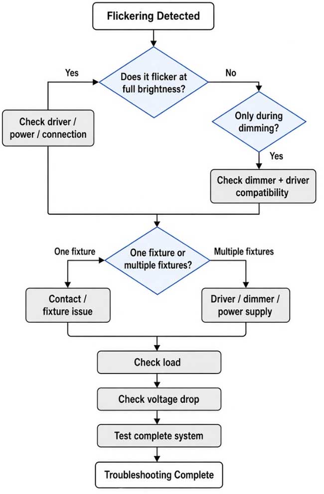
The most effective way to troubleshoot flickering is to first identify when and where it occurs. Does the flickering happen at full brightness or only during dimming? Does one fixture flicker, or do all fixtures flicker together? These details can help narrow down the cause much faster.
Common Flickering Symptoms and What to Check
Different flickering patterns can point to different parts of the lighting system.
| Flickering Symptom | Areas to Check First |
| Flickers only during dimming | Dimmer and driver compatibility |
| Flickers mainly at very low brightness | Low-end dimming performance |
| Flickers at full brightness | Driver, power supply, or electrical connection |
| Only one fixture flickers | Fixture, contact points, or individual driver |
| Several fixtures flicker together | Driver, dimmer, input power, or main connection |
| Fixtures become dimmer toward the end of the track | Voltage drop |
| Flickering appears after adding more fixtures | Driver capacity, circuit loading, or wiring |
|
Different performance under different input voltages |
Driver and dimmer compatibility |
This symptom-based approach is more useful than replacing components randomly.
1. Driver Compatibility Is One of the First Things to Check
The LED driver plays a central role in the performance of magnetic track lighting.
For a low-voltage magnetic track system, the driver must provide the appropriate output voltage and sufficient power for the connected fixtures. For example, a 24V magnetic track system requires a suitable 24V constant-voltage driver when the fixtures are designed for constant-voltage operation.
The driver should also be compatible with the required control method. A driver designed for standard on/off operation cannot automatically be assumed to perform correctly with TRIAC, 0-10V, or DALI control.
Possible symptoms of an unsuitable driver or incompatible combination include:
- Flickering
- Unstable dimming
- Limited dimming range
- Sudden shut-off during dimming
- Uneven brightness
- Unexpected behavior when the load changes
When investigating flicker, it is therefore important to evaluate the LED fixture and driver as a combination, rather than treating them as completely independent components.
2. TRIAC Dimming Requires Driver and Dimmer Compatibility
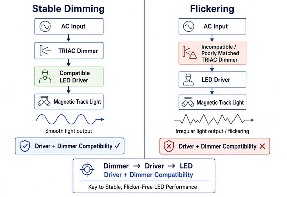
TRIAC dimming is commonly used in residential and commercial lighting, but not every LED driver is compatible with every TRIAC dimmer.
A TRIAC dimmer modifies the AC waveform supplied to the LED driver. The driver then needs to process this changing input while maintaining stable LED output.
If the dimmer and driver are not well matched, the system may show:
- Flickering during dimming
- Flickering at low brightness
- A limited dimming range
- Sudden shut-off
- Uneven brightness
- Unstable operation when the dimming level changes quickly
This explains why a magnetic track light can operate normally at full brightness but perform poorly when dimmed.
For a TRIAC-dimmable magnetic track lighting project, the actual driver and intended dimmer should be tested together.
3. Why Can Input Voltage Affect Dimming Performance?
Input voltage can influence the behavior of an LED driver, particularly when phase-cut dimming is involved.
For example, a driver may show different dimming behavior when tested under 120V and 220–240V input conditions. The result also depends on the specific dimmer, driver design, connected load, and electrical conditions.
Therefore, a test performed at 220–240V with a European-market dimmer should not automatically be used to predict the performance of the same driver in a 120V North American installation.
For a North American project, the most representative test setup is:
120V input + intended US-market dimmer + specified LED driver + representative magnetic track lighting load
This does not mean that 120V provides inherently better dimming performance. It means that the lighting system should be evaluated under the same electrical conditions expected in the final installation.
4. Check the Total Electrical Load
The total connected load is another important factor.
For a 24V system, current can be estimated using:
Current = Power ÷ Voltage
For example:
200W ÷ 24V ≈ 8.33A
At the same power:
200W ÷ 48V ≈ 4.17A
This illustrates why a higher-voltage low-voltage system can carry the same power with less current.
However, total wattage is not the only consideration. The actual design should also account for:
- Driver rated output
- Track conductor capacity
- Connector/contact rating
- Track length
- Power-feed location
- Voltage drop
- Wiring configuration
- Manufacturer specifications
The maximum allowable load should therefore be determined from the specifications of the complete magnetic track system rather than applying a universal wattage limit to all magnetic tracks.
5. Voltage Drop Becomes More Important on Long Track Runs
Voltage drop occurs because electrical conductors have resistance. As current travels through the conductors, some voltage is lost.
The effect becomes more significant when:
The track is longer
The connected load is higher
The operating voltage is lower
The conductor resistance is higher
For the same power, a 24V system draws approximately twice the current of a 48V system. For example:
200W at 24V ≈ 8.33A
200W at 48V ≈ 4.17A
With the same conductor resistance, the higher current in a 24V system can result in greater resistive voltage drop.
Voltage drop does not always produce visible flickering. More commonly, it can cause reduced brightness or uneven light output, particularly toward the far end of a long track. Under certain conditions, however, the reduced voltage may contribute to unstable operation if the driver or LED load is sensitive to the available voltage.
For longer magnetic track installations, power-feed location, track length, total load, and conductor characteristics should therefore be considered together.
6. Check the Magnetic Track Electrical Contacts
Magnetic track lighting uses electrical contacts between the lighting fixture and the track. These contacts need to maintain a stable electrical connection during operation.
A poor or intermittent contact can cause unstable lighting or intermittent flickering.
When only one fixture is affected, check:
- Fixture contact points
- Fixture installation
- Track surface and contact condition
- Track connectors
- Power-feed connections
- Track joints
A useful troubleshooting rule is:
One fixture flickering → check the fixture and its local connection first.
Multiple fixtures flickering together → check the driver, dimmer, power input, and main track connection first.
This simple distinction can significantly reduce troubleshooting time.
7. Why Does Flickering Sometimes Appear Only at Low Brightness?
Low-level dimming can be more demanding for an LED driver than operation at full output.
When the dimming level becomes very low, the driver must maintain stable LED operation under a reduced control input or output condition. The actual minimum stable dimming level depends on the driver design and the selected control method.
If a driver and dimmer are not well matched, flickering may become noticeable near the lower end of the dimming range even though the light operates normally at higher brightness.
For this reason, dimming performance should be tested across the intended operating range:
100% → medium brightness → low brightness → minimum stable output
The minimum usable dimming level should be determined from actual testing rather than assuming that every LED system can dim smoothly to 0%.
9. A Practical Flicker Testing Process
Step 1: Establish a Baseline
Start by operating the magnetic track lighting at full brightness without dimming.
Record whether the lighting is stable before introducing any dimming or additional fixtures.
Step 2: Change One Variable at a Time
Keep the track, fixtures, and driver unchanged while testing one variable at a time, such as:
Input voltage
Dimming device
Dimming level
Number of connected fixtures
Changing several components simultaneously can make it difficult to determine which factor caused the change in performance.
Step 3: Compare Different Dimming Levels
Test the lighting at several brightness levels rather than only checking maximum and minimum output.
For example:
100% → 75% → 50% → 25% → minimum stable level
Record the point at which flickering first becomes visible.
Step 4: Compare Different Load Conditions
Start with one fixture and gradually increase the number of connected fixtures.
If the lighting remains stable with one fixture but becomes unstable as the load increases, the power supply, driver capacity, track loading, or electrical distribution should be investigated.
Step 5: Check Different Positions on the Track
Compare fixtures located near the power input with those farther away.
If the fixtures at the far end show lower brightness or different behavior, measure the voltage at different points along the track to determine whether voltage drop is contributing to the problem.
Step 6: Compare the Actual Project Conditions
Finally, reproduce the electrical conditions expected in the final installation.
This approach helps distinguish between a fixture problem, driver issue, dimming compatibility problem, load-related issue, and track-level electrical problem.
10. How to Prevent Flickering in a Magnetic Track Lighting Project
Preventing flickering during the design stage is generally easier than troubleshooting it after installation.
Match the System Voltage
Make sure the magnetic track, LED fixtures, and driver are designed for the same operating voltage.
Select the Correct Driver
Choose the driver according to its output voltage, rated power, input voltage, dimming capability, and manufacturer's specifications.
Match the Dimming Method
For TRIAC, 0-10V, or DALI projects, use a driver designed for the required control method and verify compatibility before installation.
Calculate the Total Load
Consider the total connected wattage as well as the rated capacity of the driver, track conductors, connectors, and power-feed components.
Consider Track Length and Voltage Drop
For long or high-load installations, consider voltage drop during the initial design. Power-feed location and additional feeding points may need to be evaluated according to the specific track system.
Test Before Installation
Before mass installation, test a representative configuration using the intended input voltage, driver, control device, track, and lighting load.
For dimmable projects, test the complete dimming range rather than checking only whether the lights can turn on and off.
FAQ
Is 48V better than 24V for long magnetic track lighting?
For the same power and conductor resistance, a 48V system draws less current than a 24V system. Lower current can reduce resistive voltage drop. The appropriate voltage still depends on the complete track, fixture, driver, and project design.
Why does only one magnetic track light flicker?
If only one fixture flickers while other fixtures remain stable, check the individual fixture, its electrical contacts, connector, and driver first. A local connection or fixture issue is more likely than a problem affecting the entire circuit.
How can I test a magnetic track lighting system before installation?
Use a representative setup containing the intended input voltage, LED driver, dimmer or control system, magnetic track, and expected fixture load. Test the system at full brightness and throughout the required dimming range. For longer track runs, voltage at different points along the track can also be checked.
What is the most important step when troubleshooting flickering?
Start by identifying when the flickering occurs and how many fixtures are affected. Whether the problem appears at full brightness, only during dimming, on one fixture, or across the entire track can quickly narrow down the likely cause. From there, check the driver, control method, input voltage, load, electrical connections, and voltage drop systematically.