The selection of soil EC sensors suitable for agricultural applications requires a comprehensive consideration of several factors. The following are some key points:
Measurement range: Generally speaking, the measurement range of 0-20000μS/cm can cover most soil types, from mild salinization to severe saline-alkali land, which can meet the needs of most agricultural scenarios.
Measurement Accuracy:For most agricultural applications, sensors with an accuracy of ±3% within the range of 0-10,000 μS/cm and ±5% accuracy within the range of 10,000-20,000 μS/cm can meet the requirements. However, in scenarios with higher precision demands such as scientific research, more accurate sensors like the OSA-6 soil conductivity sensor should be selected, which achieves measurement accuracy of ±2%.
Resolution:High resolution can clearly distinguish the small changes of soil EC value. Generally, the resolution is 10μS/cm in the range of 0-10000μS/cm, and 50μS/cm for the sensor in the range of 10000-20000μS/cm is more ideal.
Temperature compensation function: soil EC value is greatly affected by temperature, so it is very important to choose a sensor with automatic temperature compensation function, which can ensure accurate measurement of soil EC value in different temperature environments. For example, SEN0603 RS485 soil sensor has memory temperature compensation function, and the compensation range is 0-50°C.
Common output signal types include voltage signals (e.g., 0-2V,0-5V,0-10V), 4-20mA current loops, and RS485. For applications requiring long-distance data transmission or IoT integration, RS485 sensors that support standard Modbus-RTU protocols are particularly suitable. These sensors offer strong anti-interference capabilities and facilitate system integration.
Protection class:In agricultural environment, the sensor may need to be directly buried in the soil, so the protection class should be high. Generally, the sensor with protection class up to IP68 should be selected, which can ensure that the sensor has good waterproof and corrosion resistance performance, and can work stably for a long time in the harsh soil environment.
Probe Material: The probe material should possess excellent corrosion resistance and conductivity. Common materials include 316 stainless steel and graphite. For example, the probe of the SEN0603 RS485 soil sensor is made of 316 stainless steel, which features rust prevention, waterproofing, corrosion resistance, and salt-alkali resistance, allowing long-term burial in soil.
Data storage capacity:If it is necessary to monitor the soil EC value for a long time and it is not convenient to transmit the data in real time, it is more appropriate to choose the sensor with large data storage capacity. For example, if the sensor can store more than 300,000 pieces of data, it can meet the data recording needs of large-scale plots and long-term projects.
Power supply mode: Select the appropriate power supply mode according to the use scenario. If it is in a greenhouse with stable power supply, sensors with DC power supply (such as 12V,24V) can be selected; if it is in an outdoor environment without power supply, low-power sensors with battery power or solar power can be considered.
Water is the source of life and the foundation of ecology. From rivers, lakes, and seas to the faucets of thousands of households, the safety of water quality is directly related to ecological security, people's health, and sustainable economic and social development. In the past, monitoring water quality was a tedious and time-consuming task that required manual sampling and laboratory analysis. It was not only inefficient, but also had pain points such as data lag and weak representativeness. Nowadays, with the rapid development of technology, a "smart eye" that integrates multiple functions - a water quality multi parameter sensor - is completely changing the way we perceive and understand the water world.
1、 What is a water quality multi parameter sensor?
The water quality multi parameter sensor is a highly integrated intelligent monitoring device that can simultaneously, continuously, and in situ measure multiple key physical, chemical, and biological indicators in water using advanced sensing technology.
Its core charm lies in the integration of "multiple parameters". In traditional methods, measuring pH value, dissolved oxygen (DO), conductivity (TDS), turbidity, etc. requires different instruments and reagents. Multi parameter sensors ingeniously integrate multiple independent sensor modules into a probe or a compact system, allowing for a complete set of water quality data to be obtained with just one deployment, greatly improving monitoring efficiency and convenience.
Common core monitoring parameters include:
Physical indicators: temperature, turbidity, conductivity (total dissolved solids TDS can be calculated).
Chemical indicators: pH value, oxidation-reduction potential (ORP), dissolved oxygen (DO).
Comprehensive indicators: chemical oxygen demand (COD), ammonia nitrogen (NH3-N), nitrate (NO3-), chlorophyll-a, blue-green algae, etc. (specific sensor modules are required).
2、 Core technology principles and advantages
The technological cornerstone of multi parameter sensors is various advanced sensing technologies, such as photoelectric sensing, electrochemical sensing, ultrasonic sensing, etc.
PH sensor: Typically, the glass electrode method is used to measure the hydrogen ion concentration by measuring the potential difference on both sides of the glass film.
Dissolved oxygen sensor: The mainstream method is fluorescence quenching (optical method). The fluorescent substance on the surface of the sensor is excited by light of a specific wavelength, and the concentration of oxygen in the water affects the fluorescence intensity and lifetime. By measuring these changes in optical properties, the dissolved oxygen content can be accurately calculated. This method does not require electrolyte, requires minimal maintenance, and has high stability.
Turbidity sensor: It often uses the principle of 90 ° or 180 ° scattered light to emit a beam of light and measure the intensity of light scattered by suspended particles in water, thereby determining the degree of turbidity of the water.
Conductivity sensor: Based on Ohm's law, its conductivity is calculated by measuring the resistance of water between two electrodes.
Its significant advantages lie in:
Real time and continuity: Provides a 7x24 hour uninterrupted data stream that can capture transient and sudden abnormal changes in water quality, which cannot be compared to manual sampling.
In situ monitoring: Sensors are directly placed in the tested water body, avoiding potential qualitative changes that may occur during sample transportation and storage, resulting in more authentic and representative data.
High efficiency and low cost: One machine can be used for multiple purposes, saving the cost and time of frequent sampling and extensive laboratory analysis. In the long run, the comprehensive benefits are extremely high.
Integration and Intelligence: Deeply integrated with modern Internet of Things (IoT) technology, data can be transmitted in real-time to cloud platforms through wireless technologies such as 4G/5G, LoRa, NB IoT, etc., enabling remote monitoring, big data analysis, and intelligent warning.
3、 Widely applicable scenarios
This' Eye of Wisdom 'is playing a crucial role in various industries:
Environmental monitoring and ecological protection: used for long-term ecological monitoring of rivers, lakes, reservoirs, oceans and other water bodies, assessing environmental risks such as eutrophication and algal blooms, and providing data support for governance decisions.
Smart City and Water Management: Installed at the inlet, process treatment unit, and outlet of water plants to achieve closed-loop monitoring of water quality throughout the entire process, ensuring the safety of drinking water; Used for monitoring the inflow and outflow of urban drainage networks and sewage treatment plants to improve operational efficiency.
Aquaculture: In high-density aquaculture ponds, key parameters related to fish survival such as pH and dissolved oxygen are monitored in real-time. Once abnormal, an alarm is immediately triggered and equipment such as aerators can be linked to effectively avoid risks and reduce economic losses.
Industrial process and emission monitoring: In industries such as food, pharmaceuticals, and chemicals, monitor the quality of water used in production processes; At the same time, strict monitoring of wastewater discharge from enterprise sewage outlets to ensure compliance with standards is the "frontline sentry" of environmental protection supervision.
Scientific research and hydraulic engineering: providing high-frequency and high-precision raw data for scientific research in fields such as hydrology, geology, and environment; Used for ensuring water quality and safety in large-scale water transfer projects such as the South to North Water Diversion Project.
4、 Challenges and Future Prospects
Despite its outstanding advantages, multi parameter sensors also face some challenges: biofouling can affect sensor accuracy, requiring advanced anti pollution materials or automatic cleaning devices; The complex water environment places higher demands on the long-term stability and anti-interference ability of sensors; Meanwhile, the high initial investment and professional maintenance requirements have also to some extent limited its popularity.
Looking ahead to the future, the development of multi parameter water quality sensors will present the following trends:
Miniaturization and lower power consumption: Sensors based on MEMS (Micro Electro Mechanical Systems) technology will be smaller and more energy-efficient, suitable for mobile monitoring platforms such as drones and underwater robots, as well as long-term unmanned scenarios.
Higher integration and more parameters: In the future, a sensor may be able to integrate dozens of monitoring functions, even including difficult to measure indicators such as heavy metals and organic pollutants.
Self cleaning and self calibration: The application of intelligent materials and new technologies will effectively solve the problem of biological pollution and achieve self diagnosis and automatic calibration of sensors, greatly reducing maintenance costs.
Deep integration of artificial intelligence: Combining AI algorithms, sensors can not only provide data, but also perform trend prediction, pollution tracing, and intelligent diagnosis, moving from "perception" to "cognition" and "decision-making".
Conclusion
The water quality multi parameter sensor, the "smart eye" that insight into the water world, has become an indispensable core infrastructure for building digital water management and smart environmental protection. It makes the previously invisible changes in water quality clear, visible, manageable, and controllable. With the continuous evolution of technology and the continuous decline of costs, it will inevitably integrate deeper and wider into our lives, providing unprecedented powerful momentum for safeguarding that clear water and ensuring global water security.
Is Real-Time Water Quality Monitoring Worth It for Modern Water Management
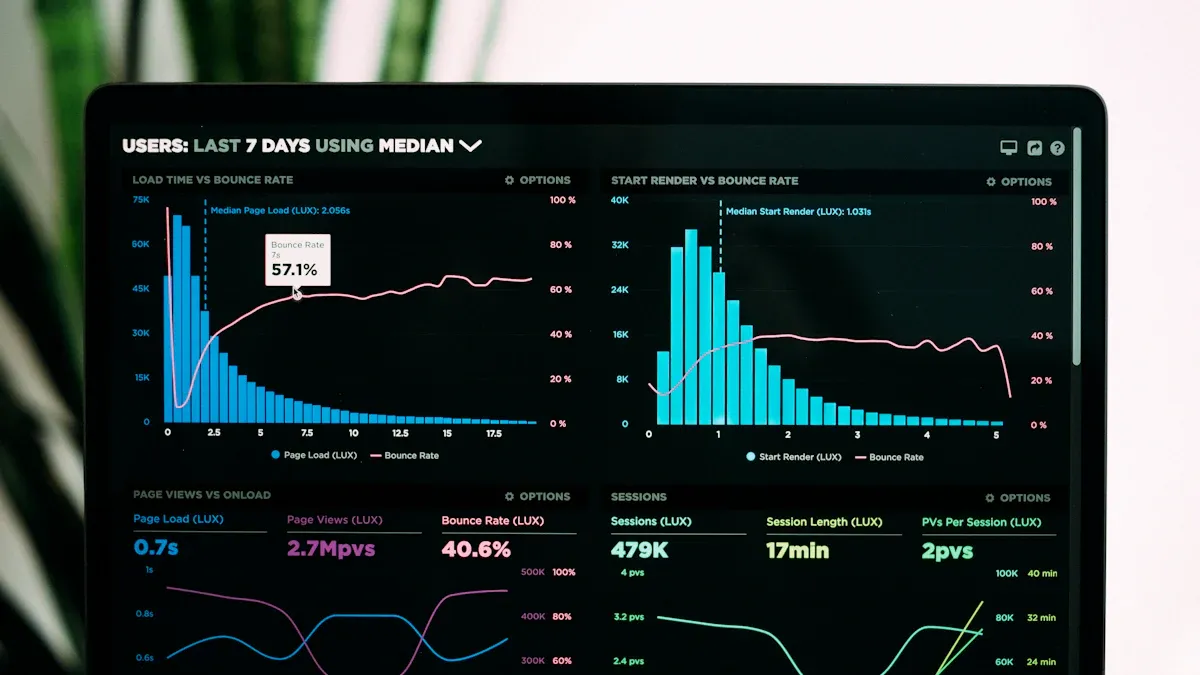
I think real-time water quality monitoring is a helpful tool for modern water management. Many utilities around the world use real-time systems. Over 63% have started using them, as shown below:
Region
Adoption Percentage of Real-Time Water Quality Monitoring Systems
Global Utilities
Over 63%
Europe
About 61%
Asia-Pacific
Over 54%
Middle East & Africa
Around 41% (new projects)
Urban Utilities
Over 62%
Industrial Facilities
39%
From what I have seen, real-time sensors for water quality give these main benefits:
I get fast data and early warnings about water problems.
I can make better choices because I see data all the time.
I save money compared to using lab tests.
But there are also some problems:
The costs are high, and the technology is hard to use and keep working.
I have to protect the data and make sure the sensors work well.
Real-time water quality monitoring gives quick data and early warnings. It helps people find problems fast and keep water safe. Continuous monitoring helps people make better choices. It shows how water changes over time. It also helps find pollution sources early. Modern sensors check many water quality factors at the same time. This gives a complete view and saves time and money. Setting up real-time systems can cost a lot and be hard to do. You need skilled workers and regular care to keep sensors working right. Picking the best monitoring method depends on your goals, budget, and water conditions. This helps manage water well and keeps people healthy.
Benefits of Continuous Water Quality Monitoring Systems
Continuous water quality monitoring systems help me manage water better. These systems give me real-time data, so I always know what is happening. I do not have to wait a long time for lab results. Before, I sent samples to a lab, and it took about 4.6 days. Now, with real-time sensors and artificial intelligence, I get alerts in about 2.7 days or even faster. I can find problems like contamination right away. This helps me act fast to keep people and the environment safe.
These systems use sensors that collect data all the time. The sensors send real-time data to my computer or phone. If something changes quickly, I get an alert. I do not worry about missing a problem because the system watches the water for me. There are fewer mistakes because the sensors work by themselves. I do not have to worry about human error or sample contamination. This makes my monitoring more accurate and reliable.
Tip: Real-time data collection helps me stop water quality threats before they get worse.
Improved Decision-Making
When I get real-time data from continuous water quality monitoring systems, I make better choices. I can watch how water quality changes over time. I see patterns and find where pollution comes from. This helps me know when to act and what to do. I work with others, like government agencies and researchers, who also use this data. Together, we protect public health and the environment.
Here are some ways real-time data helps me make better decisions:
I do not wait for lab results, so I act before things change.
I find threats to water systems and public health early.
I share instant data with others, even if they are far away.
I follow rules from local, state, and federal agencies.
I build stronger water systems that can handle emergencies.
I have seen real examples where continuous water quality monitoring systems made a big difference. At Edgewater Beach, real-time monitoring helped find bacteria problems fast. In the Clinton River watershed, I used real-time data to respond to storms and protect water quality. These systems also help me try new technologies and grow my monitoring network.
Note: Checking water quality monitoring data often helps me make smart, evidence-based choices for water management.
Comprehensive Parameter Detection
Continuous water quality monitoring systems let me measure many things at once. I use sensors that check physical, chemical, and biological parameters. This gives me a full picture of water quality. I can see changes in pH, temperature, turbidity, and conductivity. I also track chlorine, nitrogen, and bacteria like E. coli.
Here is a table showing what I can detect with modern continuous water quality monitoring systems:
I use iot-based monitoring to connect these sensors to the internet. This way, I get real-time data from many places at once. I can map water quality changes and find problems faster. Iot-based monitoring also helps me keep my data safe. I use encryption and access controls to protect important information. I can even let the public help with water quality monitoring through citizen science projects.
Iot-based monitoring gives me 24/7 access to water quality data.
I use advanced platforms for data visualization and early warnings.
I save money by using fewer people and more automation.
I keep my data safe with strong cybersecurity measures.
With continuous water quality monitoring systems, I help manage water in a smart way. I make sure water stays safe, clean, and good for everyone.
Challenges of Water Quality Monitoring
High Costs and Maintenance
When I started learning about water quality monitoring, I saw it was expensive. Setting up a real-time system means buying special equipment and building things to hold it. I also need to train people to use the system. For small towns or businesses, these costs can be too high. Even a simple IoT-based water quality monitoring system can cost more than $2,400 just for the hardware. If I want more features or more places checked, the price goes up.
Old water quality monitoring systems need a lot of money at the start. I have to pay for tools, putting them in, and sometimes new buildings for the equipment. After that, I still pay for regular care, fixing, and skilled workers to keep it working. Manual sampling costs more because it takes time and people.
Now, some companies let me rent everything with a monthly fee. This is called Infrastructure as a Service (IaaS). The fee covers hardware, software, care, training, and supplies. I do not need to buy new equipment or pay for repairs. The monthly fee also pays for internet, so I do not get extra bills. If I want to check new things in the water, I can add them without buying new sensors.
Here is a table that compares the old way and the IaaS way:
Cost Factor
Traditional Model
IaaS Model
Upfront Equipment
High
None
Maintenance
Separate, ongoing
Included in monthly fee
Calibration
Manual, frequent
Automated, less frequent
Consumables
Extra cost
Included
Connectivity
Extra cost
Included
Flexibility
Low
High
Smart sensors, like dissolved oxygen sensors, need less care than old test kits. These sensors can work for months without cleaning or fixing. They use less power and can even clean themselves. This saves time and money, but I still need someone who knows how to set up and check the system.
Note: Even with new ways and smart sensors, water quality monitoring still needs regular care and skilled workers to keep it working well.
Technical Complexity
Water quality monitoring is now more advanced, but also harder to use. I need sensors that can measure many things, like pH, dissolved oxygen, and bacteria. These sensors must work all the time, even in tough places. Sometimes, algae and dirt build up on the sensors. This is called biofouling. It can make the readings wrong and the data less useful.
Some sensors use special lights or brushes to clean themselves. For example, the UviLux sensor uses UV light to stop biofouling. Other sensors can go up to two years without needing calibration. This helps, but I still need to check them and make sure they work right.
Here are some technical problems I face with water quality monitoring:
Sensors must work well in all weather.
I need to collect data all day and night.
It is hard to find where pollution comes from, especially in rivers or near the sea.
I need to make sure the data is right and the sensors are set up well.
Sometimes, I need to fix broken parts or change cables.
I also need people with special skills to set up, fix, and check the sensors. These experts help me follow the rules and keep the system working. In some places, it is hard to find people with the right skills, which makes it harder to use advanced water quality monitoring systems.
Tip: Training and help are important to make sure my water quality monitoring system works well and gives me good data.
Data Management Issues
When I use continuous water quality monitoring, I get lots of data. Managing this data can be hard. Sometimes, algae or other tiny things grow on the sensors and cause bad readings. I use sondes with wiper brushes to clean the sensors and keep the data right.
Other problems are broken parts, old equipment, and cable problems. These issues can stop the sensors from sending data. I also have to deal with new rules and laws, so I need technology that can change when needed.
Here are some common data management problems I face:
Biofouling on sensors causes bad data.
Broken equipment means missing data.
New laws make me change how I collect and store data.
Bad calibration or wrong settings waste time and money.
Training is needed so everyone knows how to use the equipment and understand the data.
To handle all this data, I use cloud-based platforms. These tools help me store, study, and see the data from my water quality monitoring system. I can spot trends, get alerts, and make choices faster. Some platforms use smart technology to find problems before they get worse. They let me check my data from anywhere, using my phone or computer.
Callout: Smart data platforms help me handle lots of data, cut down on problems, and keep my water quality monitoring system working well.
When I pick a water quality sensor, I check what it measures and how well it works outside. There are many sensor types, and each does something different. Some sensors use light to find particles in water. Others use electricity or even living things to spot problems. I often use more than one sensor to get a full idea of water health.
Here is a table that lists the main sensor types and what they measure:
Sensor Type
Parameters Measured
Application/Notes
Temperature Sensors
Water temperature
Non-contact infrared measurement for process control
pH Sensors
Acidity/alkalinity (pH)
Maintains balanced water chemistry
Dissolved Oxygen Sensors
Oxygen levels
Monitors aquatic ecosystem health
Conductivity Sensors
Water conductivity (salinity)
Detects changes in salinity
Turbidity Sensors
Water cloudiness (suspended particles)
Assesses water clarity and quality
ORP Sensors
Oxidation-Reduction Potential
Evaluates water's ability to break down contaminants
I use water quality sensor technology to watch pH, dissolved oxygen, temperature, and turbidity. Some sensors, like ultrasonic and digital thermometer sensors, help me check distance and temperature. Biosensors use living things to find certain pollutants. Each water quality sensor has good points and weak points. Dissolved oxygen sensors are very good at finding low oxygen, so I can spot pollution. Turbidity sensors show if there are lots of particles, but sometimes harmless things can change the reading.
Tip: I always pick the water quality sensor that fits the problem I want to fix.
Calibration and Reliability
To trust my water quality sensor data, I need to keep the sensors calibrated. I usually calibrate pH, dissolved oxygen, and turbidity sensors every month. If the water is dirty or the sensors are old, I calibrate more often. Optical sensors, like dissolved oxygen sensors, stay accurate longer and do not need as much calibration. Electrochemical sensors, like pH sensors, can drift and need more checks.
Things in the environment can make my sensors less reliable. Very hot or cold weather, algae, and chemical spills can hurt a water quality sensor or make it give wrong numbers. I put my sensors in places with shade and not too much water flow. I store them in cool, dry spots when I am not using them. Cleaning and fixing sensors quickly helps them last longer.
I look for sensor drift and fix problems fast.
I use certified standards when I calibrate.
I keep records to make sure my water quality sensor data is right.
Note: Good sensors and regular calibration help me trust my water quality monitoring results.
Real-World Applications
Municipal and Industrial Use
Continuous water quality monitoring systems have changed how cities and factories handle water. In city water utilities, I use real-time monitoring to keep drinking water safe. Some systems use live Bluegills as biological indicators. These fish help me find over two thousand toxic chemicals fast. The BG-n system uses the breathing of Bluegills to spot very small amounts of contaminants. This method gives me early warnings and helps me follow rules. It keeps people safe.
I also use remote monitoring for wastewater. When I put real-time sensors at sewer lift stations, sewer overflow events dropped by 80%. I saved 1,200 labor hours because I did not need as many site visits. Real-time alerts let me fix problems before they become spills or backups. This makes wastewater management more reliable and helps me avoid fines.
In factories, I use water quality monitoring to meet strict rules from agencies like the EPA. I track pH, turbidity, and dissolved oxygen in real time. This helps me keep wastewater safe and avoid shutdowns. Automated controls use live data to change treatment steps. This saves chemicals and helps equipment last longer. By using continuous water quality monitoring, I follow rules and work more efficiently.
Rural and Resource-Limited Settings
In rural areas, I face many problems with water quality monitoring. There is often not enough money or skilled workers. Power and internet can be a problem. Sometimes, I cannot get the right equipment or keep it working. People may worry about privacy or who owns the data. These problems make it hard to set up real-time monitoring for wastewater.
Here are some common challenges I see in rural and resource-limited places:
Not enough money or policy support
Not enough skilled workers
Problems with power and internet
Trouble getting equipment
High starting costs and infrastructure needs
Gaps in data and trouble connecting systems
Even with these problems, I have seen success with low-cost solutions. In the Lake Victoria Basin, I helped set up a wireless sensor network with cheap sensors and cellular data. This system gave real-time alerts and helped people respond to pollution faster. In another project, I used electrochemical sensors with solar power and GSM technology. The results were as good as lab equipment, but the system cost much less.
Here is a table showing some successful low-cost monitoring projects:
Location/Region
Technology/Approach
Key Outcomes/Findings
Falling Water River Watershed, USA
Low-cost real-time water level monitoring
Cost-effective for flood monitoring in resource-constrained communities.
Andean region, Venezuela
Wireless sensor network for flood alerting
Useful for regions lacking infrastructure and resources.
Dublin, Ireland
Low-cost sensor network
High accuracy compared to commercial sensors; good for watershed monitoring.
Urban stormwater systems, USA
Ultrasonic depth sensors with internet control
Real-time monitoring and remote control improved stormwater management.
By using the right technology and thinking about what the community needs, I help rural areas improve water quality monitoring and wastewater management, even when resources are limited.
Making the Decision
When to Invest
Before I pick a water quality monitoring system, I think about my goals. I make sure my plan matches what I need to do and the rules I must follow. I focus on places that pollute the most. This helps me spend money wisely and fix problems faster. Sometimes, I need to check water more after big storms because pollution can go up. I set up some sites to check often and others to watch for a long time.
Here are things I think about before spending money on real-time water quality monitoring:
I see if my plan matches my goals and actions.
I find the biggest pollution sources to focus on.
I test more when pollution is likely, like after storms.
I balance my network with quick-check and long-term sites.
I make sure I can spot changes in water quality in time.
I check my budget to see if I can test more often.
I use new tools, like remote sensors, to save money.
I pick fewer but more important sites to lower costs.
I think about cost, how often I test, and how well I can show results.
I have learned that real-time systems help more in some places than others. For example, at Lake Kinneret, many users and fast changes mean real-time systems are worth it. But at Lough Gara, high upkeep costs make it less useful. I always look at how many people use the water, how often it changes, and my budget before I decide.
Tip: I choose real-time water quality monitoring when I need quick action, have lots of users, or face pollution often. This helps me manage water better and keep people safe.
Alternatives to Real-Time Monitoring
Sometimes, I use other ways to check water quality. Lab tests are very accurate, but they cost a lot and need trained workers. I use labs when I need the best results or must test things sensors cannot find. Hybrid ways, like using a phone and test strips, let me check water outside. These ways are cheaper and easy, but not perfect for every test.
Here is a table that compares different water quality monitoring methods:
Method
Accuracy
Cost
Best Use Case
Limitations
Lab-based Testing
Very High
High
Detailed analysis, rare events
Expensive, slow
Hybrid Human–Machine (Colorimetric)
Good
Low
Field checks, resource-limited areas
Less precise for some tests
Remote-Controlled Boat System
Good
Low
Mobile sampling, hard-to-reach places
Needs operator, limited samples
I also use spot checks for short-term problems, like spills or sudden changes. This works well if I have little money, few workers, or only need to check water sometimes. For slow-changing water, like deep wells, checking once in a while is enough. If I need to see trends or act fast, I pick real-time monitoring.
Note: I pick the way that fits my needs, budget, and water type. This helps me manage water smartly and handle wastewater well.
Real-time water quality monitoring helps me get quick data and early warnings. It lets me make better choices about water. But it can cost a lot and be hard to use. There are also problems with handling all the data. I think if it is worth it depends on how big my system is and what I have. I use special tools to help me decide what to do. Robust Decision Making helps me deal with things I am not sure about and find good answers. The XLRM Framework helps me break big problems into smaller parts so I can check them better.
Framework/Tool
How It Helps Me Decide
Robust Decision Making
Handles uncertainty and finds strong solutions
XLRM Framework
Breaks down problems for clear evaluation
I always make sure I know what I want to do. I pick the best places to check water. I choose the technology that fits what I need. Doing these things helps me keep water safe and reach my group’s goals.
In traditional impressions, aquaculture is often associated with "relying on the weather" and "empiricism". Masters judge the quality of water by observing the color of the water, weather, and the behavior of the livestock. This is not only labor-intensive, but also like a gamble - a sudden deterioration of water quality can lead to the complete annihilation of the army and cause huge economic losses.
However, a silent revolution driven by the Internet of Things (IoT) and intelligent sensing technology is happening in ponds, cages, and recirculating aquaculture systems (RAS) around the world. Water quality sensors are the core of this revolution, fundamentally changing the mode of aquaculture and elevating it to an efficient, accurate, and safe modern industry.
1、 Why is water quality so critical?
Before delving into sensors, we first need to understand that water is to aquatic organisms what air is to us. The water quality parameters directly determine the survival, health, and production efficiency of aquaculture products. Several core indicators include:
Dissolved oxygen (DO): the foundation of life. Hypoxia can lead to slow growth, stress, and even widespread death.
PH value (acidity or alkalinity): It affects the metabolism and immunity of aquaculture products, and extreme pH values are toxic.
Temperature: directly affects metabolic rate, food intake, and growth rate.
Ammonia nitrogen (NH ∝ - N): Produced by the decomposition of livestock excrement, it is highly toxic and is the main stressor that induces diseases.
Nitrite (NO ₂ - N): an intermediate product of ammonia nitrogen conversion, also highly toxic.
The traditional manual detection method usually only measures 1-2 times a day and cannot capture the dynamic changes in water quality, especially during the dangerous period with the lowest dissolved oxygen at night, making it difficult for management personnel to continuously monitor.
2、 Water quality sensor: the "digital sensory" of breeders
Water quality sensors are like "underwater sentinels" that work tirelessly 24/7, continuously converting chemical and physical signals in the water into precise digital data. These sensors are deployed in the water body and transmit data in real-time to the central control platform or the breeders' mobile app through wired or wireless means.
Common types of sensors include:
Optical dissolved oxygen sensor: Based on the principle of fluorescence quenching, it is more stable and requires less maintenance than traditional electrode methods.
PH/ORP sensor: uses glass electrodes to continuously monitor the acidity and redox potential of water bodies.
Ammonia nitrogen/ion selective electrode (ISE) sensor: directly monitors the concentration of toxic non ionized ammonia.
Multi parameter water quality monitoring instrument: one probe integrated with temperature pH、DO、 Various functions such as conductivity.
3、 How to improve the efficiency and safety of aquaculture?
1. From "experience farming" to "precision farming", greatly improving efficiency
Accurate feeding: Based on real-time dissolved oxygen and water temperature data, the optimal feeding time for aquaculture can be determined. For example, increasing the feeding amount when dissolved oxygen is sufficient, and reducing or even stopping feeding when dissolved oxygen is low, to avoid feed waste and water pollution. According to statistics, this can save 10% -20% of feed costs.
Optimizing growth environment: The system can automatically record the water temperature change curve, allowing breeders to choose the season that is most suitable for the growth of breeding varieties, or create the best environment by adjusting water depth and other measures, significantly shortening the breeding cycle.
Reduce labor costs: There is no need for technicians to frequently conduct manual measurements at each pond mouth. One person can monitor large breeding areas through mobile phones or computers, greatly reducing labor intensity and labor costs.
2. Build an intelligent system of "warning regulation" to comprehensively ensure safety
7x24 hour risk warning: The system can set safety thresholds for key indicators such as dissolved oxygen and ammonia nitrogen. Once the data is abnormal, it will be immediately alerted through SMS, APP push, sound and light, etc., so that breeders can take intervention measures hours or even tens of hours before the accident occurs, turning passive remedies into active warnings.
Intelligent linkage control: The most advanced system can already achieve automatic control. When the dissolved oxygen is lower than the set value, the system will automatically turn on the aerator; When the pH value deviates from the range, the dosing system can be automatically activated. This kind of immediate response is something that humans cannot achieve and can effectively avoid major accidents such as nighttime hypoxia.
Traceability and decision support: All historical data is fully recorded, forming a 'breeding log'. If there is a problem, it can be traced back to analyze the trajectory of water quality changes and quickly locate the cause. Meanwhile, big data analysis can help optimize breeding strategies and provide scientific basis for future production plans.
Ensuring product safety and sustainability: Good water quality means reducing the occurrence of diseases, thereby reducing the use of antibiotics and chemical drugs, and ensuring the quality and safety of aquatic products from the source. At the same time, precise feeding and medication also reduce pollution to the surrounding environment, making aquaculture more environmentally friendly and sustainable.
4、 Future Trends and Challenges
In the future, water quality sensing technology will develop towards greater precision, durability, and lower cost. The combination with artificial intelligence (AI) will be the next trend - AI models can not only provide early warning, but also predict the trend of water quality changes in the future by analyzing historical data and real-time information, truly achieving intelligent management.
Of course, challenges still exist, such as the problem of long-term biological pollution (scaling) of sensors underwater, and the threshold for initial investment costs for small and medium-sized farmers. But with the popularization of technology and the decrease in cost, water quality sensors will inevitably become a standard configuration for every modern breeder, just like smartphones.
Conclusion
The water quality sensor may seem like a simple data collection device, but it is a key bridge connecting traditional aquaculture and smart agriculture. It endows breeders with the ability to perceive the underwater world, transforming the breeding process from a vague "art" to a clear "science". Embracing this new trend is not only a business decision to enhance profitability, but also a necessary path towards responsible, sustainable, and safe modern aquaculture.
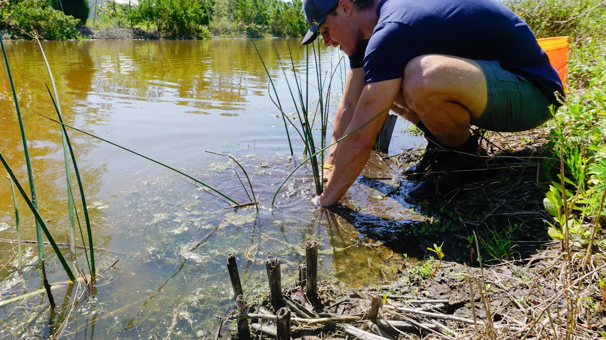
Imagine a scene like this: after a rainstorm, can the water source of remote villages be safe to drink? Has the chemical spill caused pollution to nearby rivers due to a sudden environmental accident? How can a scientific expedition team quickly evaluate the water quality of a newly discovered stream in the deep mountain jungle?
In the past, answering these questions required a long and tedious process: collecting water samples, carefully sending them back to distant laboratories, and waiting for days or even weeks for laboratory analysis. By the time the results come out, the situation may have already changed, missing the best opportunity for warning and response.
Today, technological advancements have integrated powerful laboratory analysis capabilities into a compact device that can be held with one hand - portable water quality sensors, which are fundamentally changing the way we perceive and respond to water environments, becoming an indispensable tool in the hands of field workers and emergency responders.
1、 What is a portable water quality sensor?
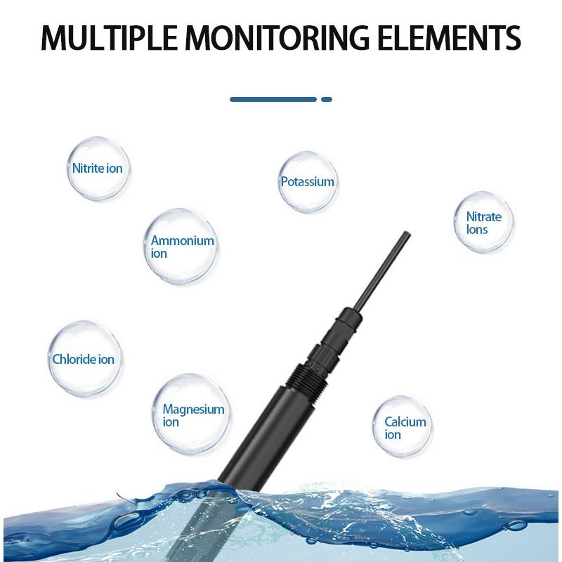
A portable water quality sensor is a precision electronic device that integrates optical, electrochemical, or biological sensing technologies. It can quickly and real-time perform on-site detection of various key indicators of water bodies, and usually has the following characteristics:
Compact and lightweight: small in size, light in weight, easy to carry and move, suitable for field operations.
Fast and efficient: No complex preprocessing required, detection results can be obtained within seconds to minutes, greatly improving efficiency.
Real time and intuitive: The results are directly displayed on the device's built-in screen or transmitted to smartphones and tablets via Bluetooth, achieving data visualization.
Multi functional integration: A device can often measure multiple parameters simultaneously, such as pH value, dissolved oxygen (DO), conductivity (TDS), turbidity, temperature, ammonia nitrogen, nitrate, heavy metal ions, and even specific pollutants.
Long lasting battery life: Powered by rechargeable batteries, it can meet the needs of long-term field monitoring.
2、 Why is it a 'weapon'? Analysis of Core Advantages
Mobile laboratory for field monitoring
Breaking geographical limitations: Whether it's high mountains, lakes, forests, or deserts, investigators can easily reach the site and immediately obtain data without worrying about water samples deteriorating during transportation.
Implementing grid based census: It can quickly conduct dense sampling of multiple points in an area, draw a detailed spatial distribution map of water quality, and help researchers accurately locate pollution sources or understand dynamic changes in water quality.
Improving scientific research efficiency: For field investigations in fields such as ecology, geology, and aquaculture, it can instantly determine whether the water environment is suitable for research or biological survival, and guide the next direction of work.
The 'early warning pioneer' of emergency response
Race against time, make quick decisions: After environmental pollution accidents and natural disasters (such as earthquakes and floods) occur, time is life. Portable sensors can rush to the scene in the first time, quickly screen the types, concentrations, and diffusion range of pollutants, and provide the most critical decision-making basis for whether to evacuate the masses and how to take disposal measures.
Ensuring drinking water safety: In the event of sudden water pollution or emergency water supply guarantee in disaster areas, continuous monitoring of water sources, temporary water supply points, and water treatment effects can be carried out to ensure drinking water safety and prevent the occurrence of epidemics.
Dynamic tracking of pollution clusters: It can track and monitor along the direction of water flow, real-time grasp the movement path and dilution situation of the pollution zone, and provide data support for subsequent governance evaluation.
3、 Typical application scenarios
Environmental Protection and Scientific Research: Investigation and Routine Inspection of Water Ecology in Rivers, Lakes, and Oceans.
Emergency management: on-site investigation of sudden environmental events such as chemical spills, oil pipeline ruptures, and algal blooms.
Water conservancy and water management: protection of water sources, rapid investigation of water quality in water supply networks, and monitoring of sewage treatment plant outlets.
Aquaculture: Real time monitoring of water quality changes in aquaculture ponds, timely oxygenation or adjustment of feeding to prevent risks.
Outdoor exploration and tourism: providing preliminary assessment of water source safety for hiking and camping enthusiasts (note that civilian grade equipment is for reference only and cannot completely replace boiling or purification).
4、 Challenges and Future Prospects
Despite its outstanding advantages, portable water quality sensors also face some challenges, such as possible accuracy interference in high concentration and complex water bodies, maintenance and calibration requirements for sensor probes, and cost issues for high-performance equipment.
However, the future is full of hope. With the development of nanotechnology, artificial intelligence (AI), and the Internet of Things (IoT), the next generation of portable sensors will become more intelligent, accurate, and powerful. We can foresee:
More comprehensive functions: integrating more sensing modules, one machine can handle more comprehensive analysis.
Stronger connectivity: The detection data is automatically uploaded to the cloud platform, enabling real-time sharing and big data analysis of global monitoring data, and building a smart water environment monitoring network.
Conclusion
Portable water quality sensors are like tireless water quality "detectives", bringing analysis work that could only be done in the laboratory to any water edge that requires them. It endows us with the ability to perceive the water environment on site, greatly enhancing our initiative and adaptability when exploring and responding to water crises in the wild. Undoubtedly, with the continuous popularization and deepening of technology, this "weapon" will play an increasingly important role in protecting the source of life and safeguarding ecological security.
In a time of climate uncertainty and growing resource demands, sensor based water quality monitoring system are no longer a luxury. Modern smart water quality sensors, especially those leveraging powerful LoRaWAN water quality sensor networks, provide the continuous, actionable intelligence needed to protect public health, ensure regulatory compliance, optimize industrial processes, and safeguard fragile ecosystems. It’s the new standard for proactive water resource management.
The Power of Integrated Sensor-Based Water Quality Monitoring:
An sensor based water quality monitoring system goes beyond simple data collection. It integrates advanced sensing, secure communications, and smart analytics into a powerful decision engine:
Advanced Smart Water Quality Sensors: Our core sensing technology leverages cutting-edge electrochemical, optical, and physical measurement principles.
Key Parameters Include: Essential Metrics:
pH, Conductivity/TDS (Total Dissolved Solids), ORP (Redox Potential), Turbidity, Temperature. Key Contaminants: Dissolved Oxygen (DO), Chlorine (Free and Total), Ammonia, Nitrate, Phosphate.
Optional Specialty Detection: Fluoride, Chlorophyll-a (algae agent), Blue Green Algae (BGA), Hydrocarbons (Oil/Gas). Robust Connectivity: LoRaWAN Benefits: Our LoRaWAN water quality sensor deployments offer unmatched benefits for widespread monitoring: Long Range: Covers vast areas with minimal infrastructure (up to 15+ km in rural areas, 2-5 km in urban areas). Deep Penetration: Provides reliable signal through challenging environments such as dense urban areas or underground sites. Ultra-Low Power: Battery life is measured in years, significantly reducing maintenance frequency and costs. Scalable and Secure: Easily add thousands of sensors to a single network with enterprise-grade security. Intelligent Data Platform: Raw sensor data turned into actionable insights:
Real-time dashboard with configurable alerts and alarms for critical parameter thresholds.
Historical trend analysis and customizable reports.
Predictive maintenance insights into sensor health.
Secure cloud-based data access from anywhere.
ZoneWu’s sensor-based water quality monitoring system provides tangible value across a variety of sectors:
1. Municipal Water and Wastewater Management:
Source Protection: Continuously monitor rivers, lakes and reservoirs for pollution events (e.g. chemical spills, algal blooms). Treatment Optimization: Real-time adjustment of chemical dosage (coagulants, disinfectants) based on influent quality, improving efficiency and reducing costs. Distance Network Integrity: Detect leaks (via pressure/quality anomalies) and prevent contamination from entering. Ensure residual disinfectant levels are maintained throughout the system. Wastewater Compliance: Continuous discharge monitoring of regulatory parameters (BOD, COD, TSS, ammonia, etc.) ensures discharge permits are met and fines are avoided. Optimize aeration energy use at treatment plants.
2.Aquaculture and Fisheries:
Optimal Fish Health: Continuous monitoring of dissolved oxygen, pH, temperature and ammonia is essential to prevent fish kills and promote growth. Receive instant alerts if levels are outside safe ranges. Feed Optimization: Reduce waste and costs by correlating feeding schedules with water quality conditions that affect fish appetite. Disease Prevention: Maintain ideal water quality conditions to reduce stress and disease susceptibility.
3.Industrial Process & Wastewater Control:
Cooling Tower Management: Control scaling, corrosion, and biological growth (Legionella risk) by accurately monitoring pH, conductivity, ORP, and biocide levels. Optimize blowdown cycles. Boiler Feed Water: Ensure strict quality control (pH, conductivity, dissolved oxygen) to maximize efficiency and prevent costly damage. Environmental Compliance: Real-time monitoring of allowable parameters for industrial wastewater discharges, ensuring compliance and avoiding downtime or penalties. Early leak detection.
4. Environmental Monitoring & Research:
Watershed Health: Long-term, remote deployment of LoRaWAN water quality sensors in rivers, streams, lakes, and coastal areas to track pollution sources, nutrient loading (eutrophication), and ecosystem health trends. Agricultural Runoff: Monitor the impact of fertilizers and pesticides on nearby water bodies.
Early Warning Systems: Rapidly detect sudden pollution events or harmful algal blooms (HABs) for rapid response.
Why choose our smart water quality sensor solutions?
Our systems are engineered for reliability, accuracy and ease of deployment:
High accuracy and stability: Industry-leading sensors with advanced calibration algorithms and drift compensation provide reliable data.
Designed for harsh environments: IP68/NEMA 6P-rated enclosures, corrosion-resistant materials and biofouling mitigation options ensure performance in the harshest conditions (wastewater, seawater, industrial environments).
Easy deployment and scalability: Modular design, simple integration (Modbus, API) and plug-and-play LoRaWAN water quality sensor connectivity enable fast setup and expansion.
Total cost of ownership Low: Minimal maintenance (long sensor life, easy cleaning/calibration), ultra-low power consumption and reduced labor costs compared to manual sampling.
Global certifications and compliance: Designed and tested to relevant international standards (e.g. CE, RoHS).
Protecting public health and safety with confidence
Learn more about our water sensor products
Contact our experts, Discuss your specific monitoring challenges and goals
When I went out for a morning run, the air quality app on my phone reminded me that "today's PM2.5 index is 35, suitable for outdoor exercise"; Passing by the river next to the residential area, I saw the green data of "turbidity 0.5NTU, dissolved oxygen 8.2mg/L" jumping on the water quality monitoring screen; When buying vegetables, I heard the vendor say, 'The soil used to grow these local vegetables has been tested and the heavy metal content is completely up to standard.' Behind these familiar details, there is actually a smart city's' environmental detective team '- water quality, gas, and soil sensors working together.
The 'monitoring outpost' hidden in the corner of the city
The first time I realized the existence of these sensors was last summer when the pond next to the community suddenly became muddy. Not long after, the staff from the environmental protection department arrived with equipment, and later found out that it was the water quality sensor by the pond that had warned of the abnormal turbidity in advance. These seemingly inconspicuous small devices are actually scattered throughout every corner of the city:
Water quality sensors are rooted in rivers, lakes, reservoirs, water pipelines, and sewage treatment plants, monitoring turbidity, pH values, and pollutant concentrations like "underwater microscopes". Just like the filter element of a water purifier at home needs to be replaced regularly, the "health status" of urban water bodies also needs to be tracked in real time, and once abnormalities are detected, pollution sources can be quickly identified.
Gas sensors stand at intersections, industrial parks, and green spaces, capturing the traces of PM2.5, formaldehyde, and volatile organic compounds 24 hours a day. I remember last winter when smog was frequent, it was the data from these sensors that supported the traffic management department to promptly implement traffic restrictions.
Soil sensors are hidden underground in green belts, farmland, and landfills, quietly recording soil moisture, acidity, and heavy metal content. The intelligent irrigation system in the community can accurately water, and behind it is the soil sensor that "tells" the system when to replenish water.
When sensors work in teams
Individual sensors can only provide fragmented information, like a small piece of a puzzle. But when they are connected into a network, they can outline a complete environmental picture.
After the rainstorm last month, the gas sensor in the northwest area of the city detected a slight increase in the concentration of hydrogen sulfide in the air, while the nearby soil sensor showed an abnormally high humidity. The system immediately linked the data of the water quality sensor in the area - the original rainstorm scouring caused the seepage of an enterprise's anti-seepage pool, and the sewage seeped into the soil and released gas. This cross dimensional collaborative monitoring has increased efficiency by at least three times compared to traditional inspections.
In agricultural parks, this collaboration is more interesting: when soil sensors detect insufficient nitrogen content, the system will combine with precipitation forecasts from meteorological stations to suggest that farmers fertilize before rain; And water quality sensors monitor farmland drainage in real time to ensure that fertilizers do not excessively flow into rivers and cause pollution.
The 'smart change' we can feel
Perhaps some people may ask, are these technologies far from the lives of ordinary people? Actually, it's not like that.
Now when you open the city service app, you can see the water quality, air quality, and soil monitoring data within 3 kilometers of your home, just like checking the weather forecast. Last year, the restaurant downstairs from my house was complained about for oil fume emissions. The environmental protection department quickly identified the period of exceeding the standard based on historical data from gas sensors, avoiding disputes of "each person's own interpretation".
More importantly, these data are changing the way cities are managed. For example, based on long-term records from soil and water quality sensors, the city has re planned the distribution of green belts; By combining real-time data from gas sensors, the staggered production time in the industrial area has been dynamically adjusted.
The Future 'Environmental Neural Network'
I heard that next year the city will install more micro sensors in old residential areas, which can even monitor indoor formaldehyde and trace elements in drinking water. As these 'environmental detectives' become more sensitive and their collaboration becomes more seamless, perhaps in the future we can truly achieve a smart life of' one screen viewing the whole city, one network management covering the entire domain '.
After all, the ultimate goal of smart cities is not cold technology, but to enable everyone to live peacefully in clean water, fresh air, and safe land.
In the era we live in, opening our phones to check real-time Air Quality Index (AQI) has become a daily habit for many people. Behind this is a precise monitoring network woven from countless "electronic noses" - gas sensors. This network is guarding the breathing of the city with unprecedented density and intelligence. Today, we will delve into the large-scale sensor deployment strategies involved in building such a network and how the massive data it generates can be transformed into insights.
一、 From sporadic embellishments to a vast network: why deploy on a large scale?
Traditional air quality monitoring relies on a few national standard stations. They have high accuracy and authoritative data, but are expensive and sparsely distributed, like a few isolated points on a map, making it difficult to accurately reflect the complex and varied air quality conditions of the entire city with significant differences in neighborhoods.
Large scale deployment of low-cost sensor networks aimed at achieving:
High resolution monitoring: Refine the monitoring granularity from "city level" to "block level" or even "community level". Can capture the differences in air quality in micro environments such as school playgrounds, traffic intersections, factory areas, parks, and green spaces.
Real time dynamic tracking: High density nodes can capture the generation, diffusion, transmission, and dissipation processes of pollution clusters in real time, just like installing "GPS" on air pollution, providing the possibility for precise traceability and early warning.
Public participation and transparency: ubiquitous sensors make air quality data no longer a mysterious black box. Citizens can access hyper localized data anytime and anywhere, enhance environmental awareness, and monitor pollution sources.
Cost effectiveness: Although the accuracy of a single standard station cannot be completely replaced, the overall data value improvement of a network formed by deploying a large number of low-cost sensors far exceeds its cost, achieving extremely high cost-effectiveness.
二、 Challenges and Strategies for Deployment: How to Spread This' Network '?
Large scale deployment is not simply about filling cities with sensors, it is a complex system engineering.
1. Selection and calibration of sensors:
Core challenge: Low cost sensors, such as metal oxide semiconductor (MOS) and electrochemical sensors, are susceptible to temperature and humidity interference, exhibit drift phenomena, and have lower accuracy and stability than standard station analyzers.
Solution: Adopt the "gradient calibration" strategy. Firstly, prior to deployment, perform initial calibration in the laboratory using standard gases. Secondly, and most importantly, after on-site deployment, allow some sensor nodes to be co located with national standard stations within the jurisdiction. By utilizing machine learning algorithms and using the "true value" data from standard stations as a benchmark, continuously and dynamically calibrate the readings of a large number of low-cost sensors in the surrounding area, thereby improving the data reliability of the entire network.
2. Optimization of Node Layout:
Core challenge: With limited resources, how to choose the most representative deployment point from thousands of locations?
Solution: Combining multiple sources of data such as geographic information systems (GIS), population density, traffic flow, land use types (industrial, commercial, residential), and meteorological data (wind rose chart) for spatial analysis. Using optimization algorithms to find key locations that can maximize coverage, identify pollution gradients, and are closest to sensitive populations (such as schools and hospitals), avoiding duplication and blind spots.
3. Power supply and communication:
Choose between mains power or solar panels for power supply in urban environments.
There are various communication technology options: 4G/5G (flexible but may have ongoing costs), LoRaWAN/LoRa (long-range, low-power, very suitable for large-scale IoT deployment), NB IoT (wide coverage, multiple connections). We need to weigh the frequency and cost of data updates.
4. Hardware durability and maintenance:
Sensors need to withstand the test of sun, rain, extreme temperatures, and physical damage. It is crucial to design a waterproof, dustproof, and vandalism resistant casing.
Establish a regular inspection and maintenance mechanism, including cleaning sensors, replacing filter membranes, calibrating and repairing, to ensure the long-term stable operation of the network.
三、 From Data Torrent to Intelligent Insight: How to Analyze?
Deployment is just the first step, letting data speak is where the value lies. The influx of a series of spatiotemporal data streams into the data platform presents enormous analytical challenges.
1. Data cleaning and fusion:
Firstly, it is necessary to handle missing values and outliers (such as peaks caused by transient interference). Use algorithms to identify and repair these "noises" to ensure data quality.
Data fusion: Combining sensor data with meteorological data (wind speed, wind direction, humidity), traffic flow data, satellite remote sensing data, map data, etc., to construct a multidimensional analysis framework.
2. Spatiotemporal data analysis and visualization:
Spatial interpolation: By using algorithms such as Kriging or inverse distance weighting (IDW), discrete point data is generated into a continuous and smooth air quality distribution map (heatmap), which intuitively displays the spatial distribution of pollution.
Time series analysis: Analyze the daily, weekly, and seasonal variations of pollutant concentrations. For example, the peak of NO ₂ (nitrogen dioxide) during the morning rush hour is usually closely related to traffic emissions.
Real time pollution diffusion simulation: Combining meteorological wind field data, simulate the transmission path of pollutants, achieve "pollution traceability", and help environmental protection departments quickly locate possible emission sources.
3. Advanced applications of artificial intelligence and machine learning:
Pollution prediction: Based on historical sensor data, weather forecasts, and traffic plans, using time-series prediction models such as LSTM (Long Short Term Memory Network), predict AQI in advance for the next few hours or even days, achieving accurate warning.
Source analysis: By analyzing the concentration ratios and synergistic changes between different pollutants (PM2.5, PM10, NO ₂, SO ₂, O3, CO), using models such as principal component analysis (PCA) or positive definite matrix factorization (PMF), the contribution rates of various pollution sources (such as motor vehicle exhaust, industrial emissions, dust, and secondary generation) are estimated.
四、 Future prospects
The urban air quality sensor network is becoming increasingly intelligent. Future trends include:
Mobile monitoring: Installing sensors on buses, taxis, and shared bicycles to form a mobile monitoring network, completely breaking the limitations of geographical location and achieving true "scanning" of the entire city.
Sensor fusion and miniaturization: Integrating more types of sensors into a micro module to simultaneously monitor multiple pollutants, noise, and meteorological parameters.
Edge computing: carry out preliminary data processing and anomaly detection on the sensor side, and only transmit the most valuable information to the cloud, greatly reducing the communication and computing pressure.
Deep integration with smart cities: Air quality data will be linked with systems such as traffic signal control, urban planning, and green space construction, providing direct decision support for creating a healthier and more sustainable urban environment.
Conclusion
The construction of the urban air quality monitoring network is a perfect landing of IoT, big data, and artificial intelligence technologies in the field of environmental science. It is no longer just a tool for environmental protection departments, but has become a key nerve endings for perceiving the environment in urban "digital twins". Through large-scale, intelligent deployment and in-depth data analysis, we are finally able to see the air we breathe with unprecedented clarity, and ultimately find an effective path to protect this blue sky.
This technology makes us believe that every step towards greener and healthier cities is being accurately measured and driven.
Wireless transmission LoRa Solar water quality conductivity (EC) sensor with the core advantages of "wireless long-distance transmission, solar autonomous power supply, real-time monitoring of water quality EC value" can break through wiring and power supply restrictions, and be widely used in outdoor, remote or large-scale water quality monitoring scenarios, which can be divided into the following categories:
1、Agriculture and crop industry: ensure irrigation water security and improve crop quality
EC value can reflect the concentration of salt (such as sodium, chloride ions) and nutrients in irrigation water, and is a key index to determine whether irrigation water is suitable for crop growth. This sensor is mainly used for:
Farmland Irrigation Monitoring: Deployed in irrigation canals and reservoirs of contiguous farmlands for wheat, corn, cotton, etc., to monitor EC values in real time. If the EC value is excessively high (exceeding salt limits), irrigation strategies can be adjusted promptly (such as increasing the frequency of saline washing irrigation) to prevent crop root damage and yield reduction caused by salinity stress.
Hydroponic/Agricultural Greenhouses: These systems are installed in greenhouse drip irrigation setups and nutrient solution tanks to precisely control the EC (Electrical Conductivity) levels of irrigation water or nutrient solutions. For example, when growing tomatoes and cucumbers, maintaining specific EC ranges is crucial to ensure nutrient absorption. Sensor data can be directly linked to irrigation equipment, enabling automated regulation.
lOrchard irrigation management: deployed in the reservoir or irrigation branch of apple orchards and citrus orchards to prevent high salt irrigation water from causing yellow leaves and poor taste of fruits (such as thickened fruit skin due to salt damage in citrus).
2、Aquaculture: Regulate water environment and reduce aquaculture risks
In aquaculture, EC value is closely related to water salinity, dissolved oxygen and fertility, which directly affect the survival and growth of fish and shrimp. The application scenarios of sensors include:
Freshwater Aquaculture (Fish, Shrimp, Crab): Deploy monitoring systems in pond and cage farming areas to track EC (Electrical Conductivity) fluctuations. Sudden EC spikes may indicate infiltration of industrial wastewater or domestic sewage, or intensified eutrophication. This allows for timely alerts and prompt measures like water replacement and oxygenation to prevent pond surface flooding incidents.
Marine/Saline Aquaculture (Sea Cucumber, Shellfish, Marine Fish): Installed in tidal flats and industrial aquaculture ponds, this system continuously monitors EC levels to maintain optimal salinity. For instance, sea cucumbers thrive in water with specific salinity levels. When EC values experience abnormal fluctuations (such as sudden drops caused by heavy rainfall), the system can instantly activate salinity regulation equipment.
Seedling stage monitoring: Aquaculture seedling has very high requirements on water quality. Sensors are deployed in the seedling pool to ensure the survival rate of seedlings by stabilizing EC value (for example, shrimp seedlings are sensitive to salinity changes, and stable EC value can reduce stress response).
3、Ecological and environmental monitoring: protecting natural water bodies and warning of pollution risks
For rivers, lakes, reservoirs and other natural water bodies, the sensor can realize remote, unattended dynamic monitoring of water quality, which is specifically applied to:
Surface Water Environmental Monitoring: Deployed at critical monitoring points within river basins (e.g., river mouths, reservoir intakes, and lake shores), this system continuously transmits EC value data in real time. When EC levels spike abruptly, it may indicate illegal discharge of high-salinity/high-ionic wastewater (e.g., from chemical plants or textile dyeing facilities). Environmental authorities can swiftly pinpoint the pollution source and initiate remediation measures.
Wetland ecological protection: Install in ecologically sensitive areas such as marshes and wetland parks to monitor the EC value of water bodies to reflect the health status of wetland hydrological cycle. For example, abnormal decrease of EC value in wetland water bodies may be caused by reduced upstream inflow leading to water degradation, which can assist ecological restoration decisions.
Drinking water source monitoring: deployed in the buffer zone around drinking water sources such as reservoirs and lakes. The purity of water can be indirectly judged by the EC value (low EC value may indicate that the water is too pure and lacks minerals, while high EC value may indicate that there is pollution), so as to provide data support for drinking water security.
4、Industrial and special fields: control of wastewater discharge, ensure production safety
In industrial production, EC value is an important basis for monitoring the compliant discharge of wastewater and ensuring the stability of production process. It is mainly used in:
Industrial wastewater discharge monitoring: Installed at the discharge outlets of enterprises such as chemical, electroplating and food processing industries to monitor in real-time whether the EC value meets environmental protection standards. For instance, electroplating wastewater contains large amounts of metal ions (such as chromium and nickel), which typically have high EC values. If the levels exceed the standard, an alarm will be triggered to prevent illegal discharge.
Circulating water system monitoring: deployed in cooling circulating water systems of electric power, steel and other industries to monitor EC value to control water hardness (high EC value is easy to scale, affecting cooling efficiency), assist in adding scale inhibitors, and reduce equipment maintenance costs.
Monitoring of pure water/ultrapure water preparation: installed in the pure water preparation process of electronics and pharmaceutical industry, the purity of water is judged by EC value (the EC value of pure water is very low, usually <10μS/cm), so as to ensure that the pure water used in production meets the requirements of the process (such as ultrapure water is needed in electronic chip production to avoid ion interference).
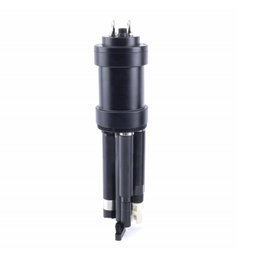
To enhance connection efficiency and maintenance convenience for industrial equipment, WAIN officially launches the M15 Quick-Connect Series. This series is designed to address major challenges in on-site installation and long-term maintenance. Its innovative structure is reflected in two core design highlights:
Core Design Highlights
Rapid Locking Mechanism for Higher Installation Efficiency
The connector housing adopts a direct-push quick-connect mechanism. During mating, no manual twisting of the coupling nut is required—simply push to engage, and it locks automatically. This significantly shortens installation time and reduces the difficulty of operating in tight or restricted spaces.
Detachable Contacts for Simplified Maintenance
The contacts use cold-crimp technology and are designed to be separable from the insert. After crimping the cable, the contact can be snapped directly into the side of the contact carrier—quick and intuitive. During maintenance, individual damaged contacts can be replaced without removing the entire connector, offering a more economical and flexible service solution.
Key Features & Advantages
1
Stable Electrical Performance
Rated at 63V / 5A, suitable for general industrial applications.
2
Reliable Connection Quality
Cold-crimped contacts ensure stable, robust performance across diverse industrial environments.
3
Flexible Model Options
Available in multiple configurations—including assembly-type (panel-mount compatible) and flange versions (front/rear panel mounting)—to support various installation needs.
4
Multiple Pin-Count Options
Offered in 9-pin, 12-pin, and 15-pin configurations to meet different signal and power requirements.
Typical Application Scenarios
◆ Industrial automation equipment (e.g., servo motors, robotic arms) ◆ Control systems requiring fast connection and easy maintenance ◆ Modular machine systems
The WAIN M15 Quick-Connect Series delivers a more efficient connectivity solution for both equipment manufacturing and on-site servicing through its optimized structural design.
For more information, please visit the WAIN official website (www.wainelectric.com) or contact us directly.
·END·
WAIN is not only manufacturing, but also creating!
Any questions and ideas related to industrial connectors,