With the rapid development of the new energy vehicle market, as a core component for energy transmission, the cost control and optimization of high-voltage wiring harnesses have become the key for automakers to enhance their competitiveness. Wire harness experts conduct an analysis from three dimensions: cost structure, quotation process, and cost reduction strategies. By integrating industry practice and technological innovation, they systematically expound the full life cycle management methods for EV high-voltage wire harnesses.


I. In-depth Analysis of High-Voltage Wiring Harness Costs

(1) Cost composition model

The total cost of HV wiring harnesses consists of material costs (73.8%), processing fees (14.7%), packaging and transportation fees (2%), and management fees (9.5%). Among them, the proportion of material costs is the highest, specifically including:

1. High-voltage connectors (55%) : They are responsible for electrical connection and signal transmission. The price difference between foreign brands (such as TE) and domestic brands (such as Luxshare) can reach 30%.

2. High-voltage cables (35%) : Copper conductor materials are dominant, with a cross-sectional area range of 16-150mm². The cost increases exponentially with the increase in wire diameter. Take a 50mm² cable as an example, the cost per meter is approximately 50 to 80 yuan.

3. Coating materials (6%) : including corrugated tubes, heat shrink tubes, etc., with a temperature resistance grade of over 150℃. Although the cost proportion is low, it affects the protective performance.

4. Other auxiliary materials (4%) : Shielding layer (aluminum foil + braided copper mesh), guard plate, etc. The material selection directly affects the EMC performance.


(II) Cost-sensitive factors

1. Wiring harness length: After the fast charging wiring harness length of a certain model was optimized from 4 meters to 2.5 meters, the cost decreased by 260 yuan.

2. Number of connectors: The high-voltage system architecture has been optimized to reduce 4 connectors, which can save 730 yuan in costs.

3. Process complexity: Replacing the crimping process with ultrasonic welding can increase efficiency by 15%, but the equipment investment increases by 20%.


Ii. Quotation Process and Key Control Points for High-Voltage Wiring Harnesses

(1) Standardized quotation process

In the requirements confirmation stage, obtain the vehicle's electrical schematic diagram, 3D wiring diagram and technical parameters (voltage level, current load, etc.).

2. Clearly define core indicators such as protection level (IP67/IP6K9K) and EMC shielding effectiveness (≥85%).

3. Use CATIA for 3D wiring simulation to avoid mechanical interference and optimize the path, reducing the length of the wiring harness by 10% to 15%.


4. Select the connector model (such as HVP800 series) and cable specification to form a BOM list.

5. Cost accounting Model:

5.1 Material cost: Calculated based on the unit price of cables (such as 70 yuan per meter for 50mm² copper cables) and the unit price of connectors (approximately 150 yuan per set for domestic products).

5.2 Processing fees: Priced by process, including crimping (0.5 yuan per point), shielding treatment (1.2 yuan per meter), etc.

5.3 Additional charges: Packaging and transportation (3-5 yuan per set), testing and certification (for example, QC/T 1037 testing fee is approximately 5,000 yuan per batch).

6. Comprehensive quotation output

6.1 Provide itemized quotations and reserve a margin of 5% to 10% for engineering changes.

(II) Key Links in Cost Control

1. Design collaboration: Conduct joint reviews with the original equipment manufacturer to avoid redundant functional designs (such as combining HVH and PTC functions to save 1.5m of wiring harnesses).

2. Supplier Management: Establish a certification system for domestic connectors (such as Ebusbar) to replace TE, reducing procurement costs by 25%.

3. Process validation: Through DOE tests, the crimping parameters (pressure of 3-5 tons, holding time of 0.5 seconds) were optimized, increasing the yield to 99.5%.


Iii. Systematic Cost Reduction Plans and Practical Cases

(1) Optimization of high-voltage system architecture

Module integration: Integrate the PDU (high-voltage distribution box) with the IPU (inverter), reducing 1.5m 50mm² cables and 2 pairs of φ8mm terminals, and lowering the cost by approximately 400 yuan per set.

Function integration: Merge the HVH (battery heating) and PTC (occupant heating) circuits, saving 1.5m of 3mm² wiring harnesses and 2 pairs of connectors, reducing costs by 130 yuan.

(2) Wiring harness layout and material optimization

Topology reconfiguration: The fast charging port was moved from the rear side panel to the front fender, and the length of the wiring harness was shortened from 4m to 2.5m, reducing the cost by 260 yuan.

Scientific selection of wire diameter: Based on thermal simulation (ΔT≤55K) and current-carrying capacity calculation, the fast-charging cable has been optimized from 70mm² to 50mm², reducing the cost per vehicle by 200 yuan.

Domestic substitution: Luxshare HVP800 connectors are adopted to replace TE products of the same specification, reducing the unit price from 220 yuan to 150 yuan, a decrease of 32%.

(3) Innovation in production processes

Automation upgrade: The introduction of a six-axis robot wiring system reduces manual intervention, increasing production efficiency by 40% and lowering labor costs by 25%.

Platform-based design: Unify the opening size of battery pack panels, be compatible with TE and Luxshare connectors, and reduce mold costs by 50%.

(4) Cost reduction through supply chain collaboration

VAVE Value Project: Jointly developed an integrated charging socket with suppliers, reducing one set of flange molds and cutting costs by 8 yuan per piece.

Large-scale procurement: Through platform-based design, the number of connector types has been reduced from 200 to 6, and the procurement cost has decreased by 18%.


Iv. Future Trends and Technological Outlook

Material innovation: Explore alternative solutions to aluminum wires. Although the cross-sectional area needs to be increased by 30%, the weight can be reduced by 45% and the cost by 50%. Anti-oxidation coating process is required.

Intelligent detection: By applying machine vision and AI algorithms to achieve online detection of terminal crimping quality, the defect detection rate has been increased to 99.8%.

Industry standardization: Promote the unification of connector interfaces (such as Tesla's announcement of six standard interfaces), reducing compatibility costs by more than 20%.


V. Expert Summary

The cost management of high-voltage wiring harnesses for new energy vehicles is a systematic project that requires collaborative optimization from multiple dimensions including design, manufacturing, and supply chain. Through strategies such as architecture integration, domestic substitution, and process upgrading, the cost of a single set of wiring harnesses can be reduced by 15% to 20%. In the future, with the innovation of materials and the application of intelligent technologies, high-voltage wiring harnesses will continue to evolve towards lightweight and high integration, providing stronger cost competitiveness for the popularization of new energy vehicles.

(Note: The data and cases in this article are based on publicly available industry research. The specific parameters are subject to the actual project.)


Introduction

At present, the competition in the domestic new energy vehicle market is becoming increasingly fierce. With the price reduction of domestic Tesla and the entry of Volkswagen's electric models, the competition will become even more intense in the future. Only by relying on high-quality, high-value products and leading technologies can automotive enterprises secure a place in the highly competitive new energy vehicle market. While major automakers are constantly innovating in technology, they are also focusing on optimizing component costs, enhancing product quality and improving corporate competitiveness. High-voltage wiring harnesses are high-value components in pure electric vehicles and are also the main parts for cost optimization.


Introduction to High-voltage Wiring Harnesses and Their Production processes

High-voltage wiring harnesses connect various components of the high-voltage system and serve as the medium for high-voltage power transmission. They are the main carrier of power output in electric vehicles and are mainly used for transmitting electrical energy and shielding external signal interference. High-voltage wiring harnesses feature high voltage, large current, high protection level and resistance to electromagnetic interference. They serve as the neural network of the high-voltage system in pure electric vehicles and are key components for the overall performance and safety of the vehicle. High-voltage wiring harnesses for pure electric vehicles are generally classified into high-voltage wiring harnesses for power batteries, high-voltage wiring harnesses for motor controllers, fast charging socket wiring harnesses, slow charging socket wiring harnesses, air conditioning system wiring harnesses, and charging high-voltage wiring harnesses. Among them, the charging high-voltage wiring harness refers to the wiring harness that connects the high-voltage distribution box to the on-board charger, air conditioning compressor, and the heater of the power battery pack.


High-voltage wiring harnesses are mainly composed of high-voltage connectors, high-voltage cables, covering materials (such as tapes, heat shrink tubes, corrugated tubes, wear-resistant self-winding tubes, etc.), and protective plates, etc. The main production process of high-voltage wire harnesses includes wire cutting, pre-installation of accessories, terminal crimping/ultrasonic welding, shielding crimping, final assembly of wire harnesses and electrical inspection.


Analysis of the cost Structure of High-voltage wiring harnesses:

The cost of high-voltage wiring harnesses consists of material costs, processing fees, packaging and transportation fees, and management fees. The material cost of high-voltage wiring harnesses is mainly determined by the technical solution of the wiring harness. Among them, processing fees include labor costs, power costs, equipment depreciation costs, and low-value consumables, etc. The material cost of high-voltage wiring harnesses accounts for approximately 73.8% of the total cost of wiring harnesses. It is necessary to continuously reduce the cost of high-voltage wire harnesses through methods such as optimizing design and production processes.


Research on Cost Optimization of High-Voltage Wiring Harnesses

There are mainly three types of methods for automotive industry enterprises to reduce costs: scale-based, supplier collaboration, and technology-based cost reduction. Among them, technology-based cost reduction is the most effective and sustainable way to cut costs. At present, there are mainly three methods for reducing costs through technology: cost benchmarking method, management technology method and technical means method. Under normal circumstances, the technical means approach includes methods such as reducing redundant functions, increasing the domestic production rate, and standardizing and platformizing specifications. In the cost reduction campaign for high-voltage wiring harnesses of pure electric vehicles, this time the main research focuses on optimizing the cost of high-voltage wiring harnesses from the following aspects through technical means. 01 Optimization of High-voltage System architecture

On pure electric vehicles High-voltage components include power batteries, three-in-one (motor controller + drive motor + differential reduction), PDU (high-voltage distribution box), ECP (electric compressor), two-in-one (IPS=OBC+DC-DC), HVH (battery heating), PTC (occupant heating), slow charging seat (ACInlet), and fast charging seat (DC) The components such as Inlet and high-voltage wiring harnesses make up the high-voltage system of the entire vehicle. A well-optimized high-voltage system architecture for pure electric vehicles can significantly reduce the number of connectors used and redundant high-voltage wiring harnesses.


02 Optimization of High-voltage wiring Harness layout

The layout of high-voltage wiring harnesses needs to be continuously optimized according to the vehicle model. After optimization, the use of high-voltage cables can be reduced, further lowering costs.

In the cost structure of high-voltage wiring harnesses, material costs account for the highest proportion. Analyzing the current situation, the main directions for material optimization of high-voltage wiring harnesses at present are the integrated design of charging sockets, the localization of high-voltage connectors, the optimization of high-voltage cable diameters, and the optimization of one-to-many material options.


03.1 Integrated design Optimization of Charging sockets

Before optimization, the charging socket was designed as a split type, which was relatively costly. The split charging socket before optimization is shown in Figure 7, including a fast charging socket and a slow charging socket. The charging sockets were developed and designed in accordance with the platform-based solution. The main structure of the charging sockets for all projects was solidified to minimize the development cost. The optimized integrated charging sockets are shown in Figure 8. This optimization can reduce one set of flange molds, thereby lowering the cost of the high-voltage wiring harness assembly by approximately 8 yuan.


Figure 7 shows the split-type charging socket before optimization


Figure 8 shows the optimized integrated charging socket

03.2 Localization of High-Voltage Connectors In recent years, the high-voltage connector industry has developed rapidly, and a number of outstanding domestic high-voltage connector brand suppliers have emerged. Before optimization, mainly foreign brands such as TE were used for high-voltage connectors. Through continuous optimization of the localization of high-voltage connectors, domestic brands like Luxshare and Ebusbar were adopted for domestic substitution, which is of great significance for reducing the cost of high-voltage connectors.


03.3 Optimization of High-voltage line cable diameter

Optimize the cable diameter of high-voltage lines through measures such as interpreting regulations, benchmarking and statistically analyzing cloud big data. For specific high-voltage cables, it is often possible to tailor them to the specific needs by optimizing the cross-section, temperature requirements, flexibility and shielding effect, to avoid excessive size and excessive components. Take the fast-charging high-voltage cable as an example. The diameter of the frontline cable was optimized to 70mm ², and after optimization, it became 50mm ², both of which can meet the actual charging requirements.


03.4 Material one-to-many optional optimization

The one-to-many high-voltage wire harness material can fully mobilize the enthusiasm of tier1 suppliers and leverage their own supply chain advantages to select the most cost-effective solution for supply. Take high-voltage cables, which account for a relatively high proportion of material costs, as an example. Currently, the main specifications of high-voltage cables are developed in accordance with the high-voltage cable standards based on the one-to-many approach. For each specification of the wire harness factory, there are multiple specifications to choose from. The specific application of conductors in each circuit needs to be confirmed based on the actual load of the entire vehicle. Through continuous optimization of design, many materials can now be selected in a one-to-many manner.


04 Platformization and standardization design:

By conducting platformization and standardization design from aspects such as the principles and raw materials of the vehicle wiring harness, the development cycle of the vehicle wiring harness design stage can be significantly shortened, repetitive verification tests can be reduced, and the cost of the wiring harness can be lowered. Through the continuous platformization and standardization of wire harness materials, the types of materials have been reduced, and increasing the quantity of a single material can achieve a scale effect, which is of great significance for reducing material costs. After research and analysis, it is found that the platformization and standardization solutions for secondary materials (connectors, cables, auxiliary materials, etc.) can significantly reduce the material costs of high-voltage wire harnesses.


Summary and Prospect

Due to the characteristics of high voltage, high current, large wire diameter and a large number of conductors, the high-voltage wiring harness of pure electric vehicles is confronted with challenges such as wiring, safety, shielding, weight and cost. As a high-value component of pure electric vehicles, high-voltage wiring harnesses can contribute to reducing the overall cost of the vehicle through continuous cost optimization through research. Cost reduction is a continuous and ongoing activity that needs to be further optimized in the future to minimize the overall vehicle cost and provide customers with more competitive products.

TXL, GXL and SXL are three common types of automotive wires, which differ in terms of material, performance and application scenarios. The following is a detailed comparison of them and a guide for selecting automotive wires:


I. Differences between TXL, GXL, and SXL

Features

TXL

GXL

SXL

Conductor cross-sectional

ultra-thin design (thinner outer diameter)

standard cross-sectional

standard cross-sectional

thickness of the insulating layer

the thinnest (about 0.64mm)

medium (about 0.76mm)

the thickest (about 0.91mm)

Temperature resistance grade

-40°C ~ 125°C

-40°C ~ 125°C

-40°C ~ 125°C

oil resistance

excellent

excellent

excellent

flexibility

High flexibility (suitable for narrow Spaces)

medium

low (harder insulation layer)

Typical applications

modern compact automotive wiring harnesses

general automotive wiring harnesses,

high-temperature or mechanical stress environments


Key differences

1.TXL Wire

  • The thinnest outer diameter and insulation layer make it suitable for modern cars with limited space (such as areas with dense electronic modules).
  • Under the same cross-sectional area, it saves 20% to 30% of space compared with GXL/SXL.

2. GXL Wire

  • Balanced design, widely used in most automotive wiring harnesses, with high cost performance.

3. SXL Wire

  • It has the thickest insulation layer and strong resistance to mechanical wear, making it suitable for high-temperature and high-vibration areas such as engine compartments.


II. Key Points for Selecting Automotive Wires

1. Current load (cross-sectional area)

  • Select the cross-sectional area of the conductor (such as 0.5mm², 1.0mm², 2.5mm², etc.) according to the current size, and refer to ISO 6722 or SAE J1128 standards.
  • For example, in a 12V system, a 1.0mm² wire can carry approximately 10A of current (for short distances).


2. Temperature resistance requirements

  • Engine compartment: Select models that can withstand temperatures above 125°C (such as SXL).
  • Interior of the carriage: TXL/GXL (resistant to 105°C to 125°C) is sufficient.


3. Environmental adaptability

  • Oil resistance/chemical corrosion resistance: Cross-linked polyethylene (XLPE) insulation materials (TXL/GXL/SXL all meet the requirements) are preferred.
  • Waterproof: It is necessary to use waterproof connectors or select special sheaths (such as GPT type wires).


4. Mechanical stress

  • For high-vibration areas (such as the chassis), SXL or braided shielding layers should be selected.
  • For high flexibility requirements (such as door wiring harnesses), TXL can be selected.


5. Standard certification

  • Complies with SAE J1128 (American standard), ISO 6722 (international standard) or national standard GB/T 25085/25087.


6. Cost and space

  • For compact design, choose TXL; for regular applications, choose GXL; and for high reliability requirements, choose SXL.


III. Other common types of automotive wires

  1. GPT: General-purpose type, with a relatively thick insulation layer, resistant to 105°C, used in non-high-temperature areas.
  2. HDT: Heavy-duty wire, resistant to high temperatures up to 150°C, used in high-voltage systems of hybrid/electric vehicles.
  3. Coaxial Cable: Used for radio frequency signals (such as GPS, antennas).


IV. Example of Selection Process

  1. Determine the circuit current → Select the cross-sectional area.
  2. Analyze the environment (temperature, oil contamination, vibration) → Select TXL/GXL/SXL.
  3. Verify whether it complies with the vehicle manufacturer's standards (such as German VW 60306, Japanese JASO).

Through the above steps, a balance can be achieved among the safety, reliability and cost of the wires.

The basic idea of automotive wiring harness design is to determine the circuit loop based on the requirements of the electrical equipment and calculate the voltage and current of each loop, especially for high-power equipment. Select the matching connectors according to the electrical equipment, determine the cross-sectional area of the wiring harness based on the current, and then design the wiring harness layout.


Overview of Wiring Harness Design

The basic process of wire harness development and design is as follows:

(1) According to the function list required by the main engine manufacturer, list all the functional components connected to the wiring harness, confirm the component functions with the corresponding electrical engineer, obtain ICD information, and determine the electrical principle layout diagram. Verify the principles of each ECU system and integrate all functional components into a completed wiring harness schematic diagram. Generally, the power supply system and the grounding part can be combined by riveting points. At the same time, check the current size of each functional system (including overcurrent or locked-rotor current, etc.) to ensure that it can meet the working requirements of electrical systems such as motors, switches, fuses, and blowers.

(2) Design the initial 3D distribution diagram. According to the processing and assembly sequence of the general wire harness process, complete the routing distribution of the wire harness using CATIA or UG software. During this process, the installation position of the fuse box needs to be basically defined, and the initial 3D distribution drawing usually reserves a certain margin.

(3) Convert 2D drawings. The 2D drawings should refer to industry standards, such as the relevant requirements in the QC29106 standard.

(4) Based on the initial 2D drawings, make manual wiring harness samples and test assemble them in the vehicle.

(5) Based on the actual trial installation results and trial operation results, the 3D wiring engineer of the wire harness is optimizing and adjusting the direction or length of the wires, taking into account dynamic conditions.

(6) Wiring harnesses are used in conjunction with the installation and connection of the vehicle's electrical functional components. Due to the installation requirements of various electrical systems or the entire vehicle, wiring harnesses generally need to be constantly adjusted and optimized in accordance with each system. That is, the entire development process is also a process of continuous optimization and update of the design.


Wire Harness Design Method

1. Principle design of wiring harnesses

(1) Request the vehicle manufacturer for the electrical functions of the entire vehicle, current requirements and other special requirements. And confirm all information such as the installation location of the electrical components, the assembly method of the electrical components and wiring harnesses, and the working environment.

(2) Based on the functions and methods that the customer needs to achieve, create electrical schematic diagrams and circuit layout diagrams.

(3) Allocate energy to each electrical component system, including the distribution of power lines and grounding wires.

(4) Determination of the wire diameter. First, the current that the wire needs to pass through is obtained from the actual power of the electrical component. Long-term working components use wires with 60% of the actual current-carrying capacity (such as heating systems, entertainment systems, and safety systems); For short-term working components, wires with an actual current-carrying capacity of 60% to 100% should be used. For example, seat adjustment motors, window lift motors, Angle adjusters, etc.

2. 3D wiring harness design

The three-dimensional layout of the wiring harness is generally carried out under the premise of meeting the installation requirements of the vehicle's electrical system, in combination with the layout of the body sheet metal and the design of openings and grooves, to achieve an overall layout. In particular, the segmented design of the wiring harness and the positioning of the main trunk should take into account the overall layout.

2.1 Requirements for Three-dimensional Wiring of Automotive Wiring Harnesses

The three-dimensional wiring of automotive wiring harnesses from existence to non-existence is a complex project, mainly referring to the following points:

(1) Ensure that all electrical functional areas are easy to assemble, and the final assembly section should be as simple as possible to facilitate installation. If there are parts that are not suitable for direct installation, it is advisable to consider installing the accessories inside, installing them separately and then assembling them together (this will increase the cost). The tail lines for door panels, interiors, etc. can be assembled separately. Try to ensure that the assembly process can be achieved through traditional technological procedures and tooling.

(2) Besides assembly, maintenance and repair should also be emphasized. It is also necessary to be easy to disassemble, which is commonly referred to as DFD (design for disassembly). During maintenance, only a section of the wire needs to be removed, which is much easier to operate than removing the entire wire harness. At the same time, it saves costs and reduces potential risks.

2.2 Other details of the wiring harness layout

In addition to the convenience of assembly and disassembly mentioned above, the wiring harness layout also needs to take into account the following details:

(1) Reserve sufficient margin (even under the lower limit of tolerance), especially for wiring harnesses between two or more components with relative motion. The length required at the limit position must be taken into consideration.

(2) The wiring harness should not remain taut all the time; otherwise, it will continuously exert internal stress on the copper sheets of the wires, accelerating their aging process.

(3) Wire harnesses generally need to be fixed at intervals with clips or slots and should not have a long free state.


Part selection

1. Wire selection of Cable Assemblies

When choosing wires for a wiring harness, the key considerations should be the functions and environments that the wiring harness needs to achieve. For instance, in the case of engine wiring harnesses, the cabin temperature is very high and there are many corrosive substances. Therefore, materials that are resistant to high temperatures and oil corrosion should be selected, such as Teflon or cross-linked PE.

The trunk or the car door moves frequently. Therefore, it is necessary to choose a wiring harness with higher elasticity, such as TPE or rubber types. For some weak signal types, composite shielded wires are generally used, such as detonation sensor wiring harnesses, etc. The requirements for the cab are relatively low. It is advisable to consider using PVC-type wiring harnesses, which can save costs and be beneficial for lightweighting.


2. Connector

Connectors are the most crucial components of wiring harnesses, directly determining whether the wiring harness can achieve the most core connection function and playing a decisive role in the stability of electrical systems.

2.1 Selection Requirements for Connectors

Firstly, it is the coordination with the electrical components. The mechanical insertion holding force should meet the usage requirements, and a design with a secondary lock should be preferred. Contact resistance should be as low as possible. The insulation resistance and overcurrent comply with the working current requirements of the conductor. For wire harnesses located in wet areas, waterproof sheaths should be selected and appropriate sealing rings or blind plugs should be matched to meet the requirements of different waterproof levels in different areas.

2.2 Performance of Raw Materials for Connectors

① Sheath material (plastic part) :

The commonly used materials for current connectors mainly include PA66, PBT, ABS, etc. Generally, some additives need to be added to enhance the performance of the materials, such as adding glass fiber to increase strength and adding plasticizers to increase softness.

② Terminal material (copper part) :

The commonly used materials for terminals are brass, bronze and copper alloys. Brass has strong wear resistance, bronze has good castability, is wear-resistant and has stable chemical properties, and copper alloys have excellent electrical conductivity, thermal conductivity, ductility and corrosion resistance. In addition, considering salt spray and aging, terminals usually need to be coated with different layers, such as tin plating and gold plating.

2.3 Connector Classification

According to the connection form of connectors, they can be classified as: wire-to-wire and wire-to-board.

① Wire-to-Wire

Wire-to-wire connection includes the form of wire-to-cable or cable-to-cable, and its defining feature is that two single individual wires or the corresponding conductors in two cables are permanently connected to each other.

② Wire-to-Board

Wire-to-board connection mainly involves one end of the connector being connected to a wire or cable, while the terminal on the other end of the connector is fixed and welded to the substrate.


Wire harness covering design

Automobile wiring harnesses are exposed to various external factors for a long time inside the vehicle, such as oil stains, dust, friction, and rusting due to water imitation. If there is no protective material on the wiring harness, the exposed wires are prone to damage, such as broken wires and short circuits, which may lead to functional failure. The commonly used materials for bandaging are as follows:

1. Corrugated pipe

Corrugated tubes are the most important wiring harness protection materials used in automotive wiring harnesses and are generally divided into single-sided opening and sealed type sleeves.

The materials used are PE, PA6/66, PP, etc. The temperature resistance is generally in three grades: -40℃ to 85℃, -40℃ to 125℃, and -40℃ to 150℃. It has good wear resistance and excellent high-temperature resistance, flame retardancy and heat resistance in high-temperature zones. PA material is better in terms of flame retardancy and wear resistance, while PP material has an advantage in terms of resistance to bending fatigue.

2. Adhesive Tape

Tape is the most widely used covering method in wiring harnesses, mainly divided into three types: PVC tape, flannel tape and fabric-based tape. PVC tape has relatively good insulation performance, with a general temperature resistance of 80℃. Even after improvement, it is usually only 105 ℃. It has poor noise reduction performance and the wiring harness is relatively hard after coating. Currently, its VOC effect is generally poor. The base materials of flannel tape and cloth tape are generally PET. Flannel tape can withstand temperatures around 105 ℃, has good noise reduction performance, and the wiring harness is relatively soft after coating. Cloth tape has the best wear resistance, generally reaching a wear resistance grade of D or E, and its temperature resistance can also reach 150 ℃. However, it is relatively expensive and is usually used in places with holes or relative movement.

3. Braided mesh pipe

The material of the braided pipe is generally made of PA66 monofilament or PET monofilament. It is usually available in open and closed types. Its feature is extremely high wear resistance, but its noise reduction performance and cost are also relatively high. It is generally used in parts that are in long-term relative motion.


Automotive wiring harnesses are known as the vascular system of automobiles. With the rapid development of automobiles and the continuous improvement of user experience, the requirements for automotive wiring harnesses are also constantly increasing. It is even more necessary for automotive wiring harness professionals to continuously research and develop new solutions in order to meet the ever-changing demands.

The MCIO cable is a connection cable based on the MCIO (Mini Cool Edge IO) interface. MCIO is a high-density, low-height, high-speed connector system that complies with the SFF-TA-1016 standard. The following is a detailed introduction to the MCIO Cable:

【Features】High-speed transmission The MCIO cable supports high-speed signal transmission and can support high-performance links such as PCIe 5.0/6.0, CXL, and UCIe. The single-channel signal transmission rate can reach up to 56 GT/s NRZ and 112 GT/s PAM-4, which can meet the interconnection requirements of next-generation servers and data centers for high bandwidth and low latency.

Compact design: The MCIO interface features a 0.6mm pin pitch and adopts a compact design. It optimizes system space while supporting high-performance data transmission, making it suitable for designs that require high-speed signal routing and management within limited Spaces.

Excellent signal integrity: The MCIO cable can maintain stable signal quality even in long signal paths, reducing signal loss and interference. Its cable design can provide an ideal long-distance high-data-rate signal transmission solution.

Strong compatibility: MCIO cables are typically designed to be backward compatible. For instance, MCIO cables that support PCIe 5.0 can also be seamlessly compatible with older versions of PCIe (4.0, 3.0, 2.0, 1.0), achieving a smooth transition between new and old technologies.

Flexible configuration: The connectors of the MCIO cable offer different configurations of plugs such as right-angle, right side exit, and left side exit, which can be matched with right-angle and vertical on-board connectors, enhancing design flexibility. At the same time, there are multiple pin configurations, such as 38-pin and 74pin, to meet the requirements of different numbers of signal channels.


【Performance parameters】Electrical performance The working voltage of the MCIO cable is generally 30VAC per contact, the current is 0.5A per contact, the initial maximum contact resistance is 20mohm, the maximum change after stress testing is 20mohm, and the minimum dielectric withstand voltage is 300VDC for 100ms. The minimum insulation resistance between adjacent pins is 10MΩ.

Mechanical performance: The insertion and extraction force of the MCIO cable has certain limitations. The maximum mating force is 55.5N, and the maximum unmating force is 49N. The minimum rated durable cycle number is 250 times.


【Application】MCIO cables, with their features such as high-speed transmission and high-density connection, have been widely applied in multiple industries including data centers, artificial intelligence, and storage

Data center industry: In data centers, MCIO cables can be used for direct connection of PCIe 5.0 SSDS, replacing traditional SAS/SAS expansion cards and reducing data transmission latency. For instance, some large cloud computing data centers, when upgrading their storage systems, adopt MCIO cables to connect the motherboards and SSD backboards, achieving faster data read and write speeds and enhancing the response efficiency of cloud services. Meanwhile, the MCIO cable can also provide high-bandwidth inter-board connections for AI training nodes, supporting multi-card collaborative computing. For instance, some of NVIDIA's data censary-level GPU servers adopt the MCIO cable to achieve high-speed interconnection between Gpus, accelerating the training process of AI models.

In the artificial intelligence industry: In AI servers, MCIO cables are used to connect cpus with Gpus or dedicated accelerators to ensure high-speed data transmission and low latency. For instance, in some deep learning-based natural language processing and image recognition servers, the CPU and GPU are connected through MCIO cables, which enables rapid processing of large amounts of data during training and inference, thereby enhancing the training speed and recognition accuracy of the model.

Storage industry: c can achieve adapter compatibility solutions, such as MCIO 8X to dual Mini SAS HD (SFF-8643) cables, which can realize the mixed deployment of new and old storage backboards, protecting the enterprise's original storage equipment investment while enhancing the performance of the storage system. Some storage device manufacturers also use MCIO to customize network card modules, supporting 100G Ethernet, which increases the data transmission bandwidth between storage devices and the network.

In the high-performance computing industry: In high-performance computing clusters, MCIO cables are used for direct connections between processors, supporting rapid data exchange and collaborative work, and reducing data transmission bottlenecks. For instance, in high-performance computing systems in fields such as weather forecasting and scientific research, by connecting multiple processors through MCIO cables, large-scale meteorological data, scientific simulation data, etc. can be processed rapidly, thereby enhancing computing efficiency and accuracy.

In the edge computing industry, MCIO cables provide the necessary high-bandwidth connections in edge computing applications, supporting real-time data processing and rapid response. For instance, in the edge computing devices of the intelligent transportation field, the MCIO cable connects processors and sensors such as cameras and radars, capable of processing the collected traffic data in real time, achieving functions like vehicle recognition and traffic flow monitoring, and providing timely and accurate data support for the intelligent transportation system.

Finding a comfortable yet capable health tracker just got easier with the HK72 smart bracelet. This ultra-light 38g wearable disappears on your wrist with its barely-there 9.9mm metal body, proving you don't need bulk for advanced features. The vibrant 1.47-inch AMOLED screen delivers crisp notifications and health data at a glance, while the 10-day battery life outlasts most smartwatches.


What sets the HK72 apart is its thoughtful health tracking. It automatically monitors your heart rate and blood oxygen around the clock, with special attention to women's health through menstrual cycle tracking. The sleep analysis breaks down your REM cycles, while the stress monitor suggests breathing exercises when tension rises. Unlike complex smartwatches, it presents this data simply through an intuitive interface.


For active users, the IP68 waterproof rating means no workout is off-limits - whether swimming laps or running in rain. The bracelet automatically detects exercise types and tracks progress through three motivational activity rings. Smart features like Bluetooth calling and offline Alipay payments add convenience without complicating the experience. With multiple stylish watch faces and an always-on display option, the HK72 blends seamlessly into both gym sessions and business meetings - a rare balance of form and function in wearable tech.

Ultra thin AMOLED smart braceletOEM smart bracelet supplierCustom logo fitness trackers

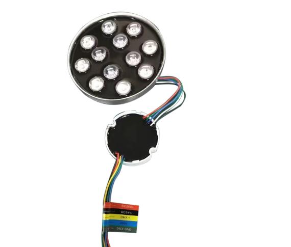
We are a factory that has designed and produced LED fountain lamps for 15 years, with a stable engineering and sales team.Over the past 15 years, we have also encountered a problem that a small number of products may stop working after a few years of use.


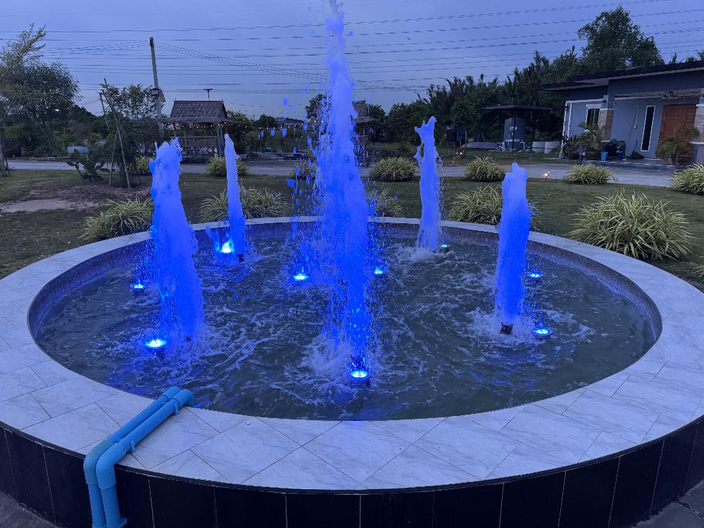
Typically, these DMX or RDM lights are installed in fountains, pools, plazas, or artificial lakes. Therefore, if a product stops working, it is a huge undertaking to maintain them. The conventional method involves draining the pool or fountain, removing and opening the device's junction box, removing the defective unit, and then rewiring and replacing it with a new one. This task becomes unimaginable in an artificial lake.


For example, Have a look next pictures, which happened in a fountain pool,All cables from light to junction box have 10 meters. However, two units lights stopped work and you must replace them.

LED Fountain pool lights


LED Swimming Pool Lights

Our team has upgraded product design, which not only improves the waterproof quality of our products, but also helps customers optimize the repair process.All our products have waterproof designs for PCB and DMX/RDM decoders. The entire PCB is mounted in a 2.5mm thick aluminum bowl for improved heat dissipation, and the PCB is sealed with IP68-rated waterproof adhesive. Similarly, the DMX/RDM decoder is housed in a white plastic bowl, also sealed to IP68 standards. As the picture we did,


Therefore, no matter how complex the environment, maintenance personnel only need to remove the light from the Nozzle in Fountain, open the lamp cover, replace the LED PCB/decoder inside, and re-tighten the cover screws evenly. which basically completes the repair work. This eliminates the need to remove the waterproof box, reconnect the power and signal cables, or even drain the water of pool.

By following a few simple steps, the fountain light can be restored to its original state.

Waterproof LED Fountain Light


Outdoor LED Fountain Light


Furthermore, for lights beyond their warranty, repair costs are minimal. Customers only need to re-purchase the PCB and DMX/RDM decoders, and several waterproof gaskets (screws are provided free of charge). Compare with purchase finished lights, Purchase cost and expensive international shipping costs can be saved, as the PCB/decoders has so light weight.

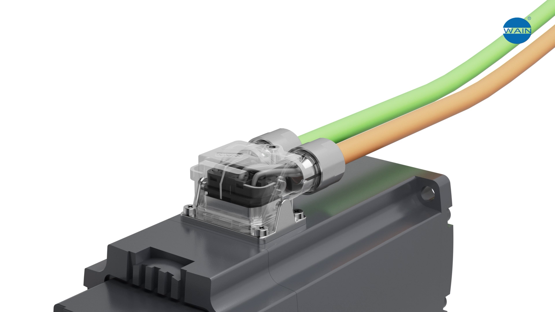
In industrial automation, robotics, and precision instruments, connector performance is often the “invisible bottleneck” that limits system reliability. Traditional connectors can be hard to route in tight spaces, difficult to service, and prone to interference. WAIN’s MI Series miniature high‑density connectors give engineers a space‑saving, easily maintained, high‑reliability alternative.

MI Series Miniature High‑Density Connectors


Break the Space Barrier 


· MI connectors feature a compact form factor that is smaller than conventional products while integrating three functional modules—signal, power, and brake—into a single unit. This eliminates cable clutter and frees up valuable enclosure space, making the connectors easy to embed in robot joints, AGV control bays, or precision-instrument compartments.

· A partitioned, removable-module design allows users to detach either the signal or power section independently. If one module fails, the entire connector does not need to be replaced, dramatically reducing maintenance time and cost. Compared with traditional one-piece connectors, service efficiency is significantly improved.


Five Core Technology Innovations


1、One-Second Quick-Release — Latch Mechanism
MI connectors use an elastic latch-lock design that mates or unmated with a single press, cutting installation time. Anti-mis-mate coding ensures precise, reliable connections.

2、Vibration-Resistant Cold-Crimp Contacts
Contacts are cold-crimped—no soldering—delivering high-strength conductivity. Tested to withstand 500+ mating cycles, ideal for high-vibration environments such as industrial robots and rail systems.

3、360° Electromagnetic Shielding + Partitioned Isolation
Dual-layer protection:
• Outer full-metal shell blocks external EMI.
• Inner isolation chambers physically separate power and signal sections, eliminating crosstalk and guaranteeing zero-packet-loss data transmission.

4、Dual-Cable Exits for Flexible Routing
Independent power and signal channels exit through Ø 7.5 mm ports, accommodating large-gauge power and fine-gauge signal wires. The plug supports 180° dual-direction swivel, adapting to varied equipment layouts.

5、Visual Assembly — Top + Side Inspection Windows
Technicians can verify pin alignment in real time, preventing bent pins from blind mating. During service, windows enable rapid fault location, lowering technical complexity and downtime.


Proven in Harsh Environments


·Operating temperature: –40 °C … +130 °C

·Ingress protection: IP67 (mated, EN 60529) – suitable for aerospace and outdoor equipment

For outdoor enthusiasts who split their weekends between trailblazing, stargazing campsites, and river kayaking, finding a watch that marries functionality with simplicity has long been a challenge. TERRAX steps in as the solution, blending practical design with a "Travel Light" ethos that resonates with those who prioritize the journey over the gadget.​


Its appeal starts with a clutter-free approach: no overcomplicated interfaces or redundant apps, just a streamlined design that lets adventurers focus on the experience rather than navigating menus. The lightweight build is a standout feature—perfect for 10-mile hikes where every ounce matters. The ultra-light nylon strap, soft yet sturdy, feels barely there, even during all-day wear.​


Small but thoughtful details elevate its usability in the wild. Physical buttons, a deliberate choice over touchscreens, ensure reliable operation whether users are wearing thick gloves mid-climb or have wet hands after a sudden downpour. When twilight fades to darkness, the military-grade green glow illuminates the entire dial, turning pitch-black forests or moonless campsites into spaces where time stays visible.​


Eco-conscious materials add depth to its appeal, aligning with the values of outdoor lovers who strive to minimize their environmental footprint. Nature-inspired color palettes—subtle greens and earthy tones—blend seamlessly with wilderness backdrops, making it as much a style statement as a tool.​


TERRAX doesn’t aim to compete with smartwatches. Instead, it excels as a reliable companion, built to keep pace with the most rugged adventures. For those who need timekeeping that fades into the background until it’s needed, it’s the perfect fit.

 Custom logo outdoor watch supplier

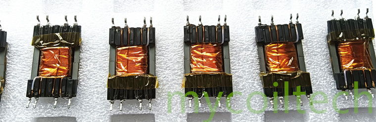
In the highly competitive electronic equipment market, a product with outstanding performance can often help you stand out. The quality of core magnetic components is crucial to the performance of the equipment. We recognize that each customer has unique needs, which is why we specialize in customizing products for you. Our offerings span transformers, high-frequency inductors, current transformers, as well as transformer bobbins, transformer clips, transformer bases, and copper wires, providing a one-stop customization service to boost your equipment's capabilities.

When your equipment demands stable and efficient voltage conversion, high-frequency electronic transformers play a vital role. While universal transformers may suffice in some cases, customized transformers can precisely match your equipment's power, voltage, and other parameters, minimizing energy loss and enhancing operational efficiency. Whether it's the strict low electromagnetic interference requirements for medical devices or the high stability needs of industrial machinery, we can optimize magnetic core materials and winding processes to make the customized transformer a reliable "energy hub" for your equipment, giving you an edge in market competition.

Customized Flyback Transformer

High-frequency inductors are indispensable in high-frequency circuits, and their performance directly impacts the signal transmission and stability of the equipment. Standardized products struggle to adapt to the varying high-frequency environments of different devices. However, our customization service can tailor high-frequency inductors based on your equipment's operating frequency, space constraints, and other factors. By precisely designing the winding method and selecting the right magnetic core, we can effectively reduce high-frequency losses, ensuring your equipment remains stable during high-speed operation, enhancing product competitiveness, and winning more customer trust.

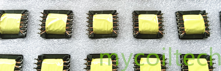
SMD servo motor driver transformer

The safe operation of power systems relies on accurate current monitoring, and current transformers are the key components to achieve this. Different power equipment has varying requirements for the accuracy and range of current monitoring, and customized precision current transformers can perfectly meet these needs. We will optimize the core design and winding turns according to your application scenarios, ensuring accurate current signals are provided under all complex working conditions. This provides strong support for the safe and stable operation of power systems, making your products more trusted in the market.

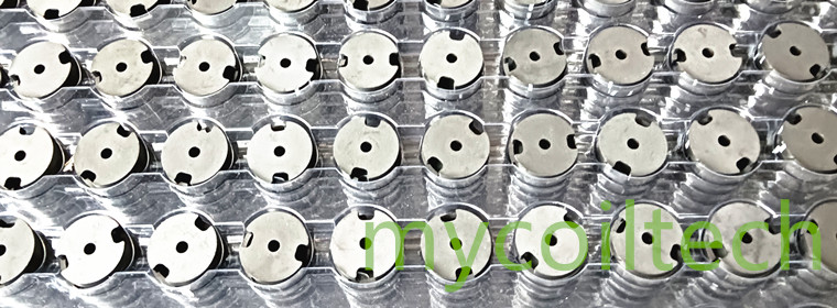
 Potting ferrite cores for transformers

High-quality transformers require support from complementary accessories, and electronic transformer bobbins are an important part of this. Customized transformer bobbins not only precisely fit the structure of the transformer to ensure stable windings but also use appropriate materials based on the equipment's working environment, improving insulation performance and durability. Transformer clips can firmly secure the transformer, preventing vibrations during equipment operation from affecting it and ensuring the transformer remains in a stable working state.

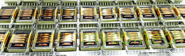
Power switch transformer

The customization of electronic transformer bases is also essential. They not only provide support but also assist in heat dissipation for the transformer. For high-power transformers, we design transformer bases with efficient heat dissipation structures to promptly dissipate heat generated during operation, extending the transformer's service life. Transformer winding wires, as the core material of transformer windings, directly affect the transformer's performance. We provide customized copper wires based on the transformer's power and current requirements, ensuring smooth current transmission, reducing energy consumption, and making your equipment more energy-efficient and effective.

From core components to complementary accessories, our customization services cover transformers, high-frequency inductors, current transformers, as well as transformer bobbins, transformer clips, transformer bases, and enameled wires. We take meeting your needs as our starting point, using professional technology and attentive service to create high-quality customized products for you, helping your equipment stand out in the market. Choose our customization service to let every component add value to your products and embark on a path to success together.


Contact us today to explore bulk orders or request technical specifications.

Email: sales008@mycoiltech.com

WeChat ID: MCT008Alex