
SFU1610 Ball Screw Linear Module The Ideal Linear Motion Solution For CNC & 3D Printing
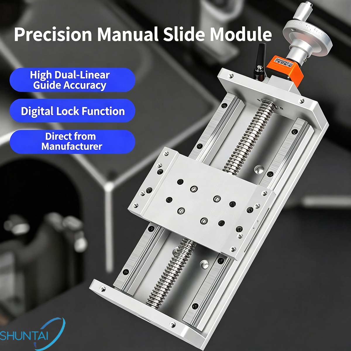
Premium Raw Materials & Precision Manufacturing
-
TBI SFS Silent Ball Screw CoreEquipped with original TBI-SFS high-speed silent ball screws, our linear stages operate with ultra-low noise even under continuous high-speed travel, ideal for workshop and lab environments requiring quiet operation.
-
High-Strength CNC Machined Aluminum BaseThe module frame uses heavy-duty aluminum alloy processed via precision CNC machining. Smooth finished surfaces and standardized mounting hole layouts lock the sliding carriage firmly in place, eliminating wobble and boosting overall structural stability during heavy-duty cycles.
-
Protective Limit Switch AssemblyPre-installed photoelectric limit switches feature reverse-polarity protection circuits. This built-in safety feature prevents over-travel damage, maximizes operational efficiency, and extends the full working lifespan of your automation equipment.Core Product Strengths For Industrial Buyers
1. High Rigidity & Multi-Directional Load Capacity
Built to match Hiwin-grade module performance standards, our SFU1610 linear slide bears heavy loads across vertical, horizontal, lateral and axial directions. The reinforced frame resists bending under heavy workpieces, making it perfect for high-load precision machining tasks.2. Ultra Long Service Life
Thanks to wear-resistant GCr15 bearing steel screw and guide rail components, this linear motion system withstands thousands of continuous working hours without noticeable loss of positioning accuracy, reducing your long-term maintenance and replacement costs.3. High Position Resolution & Stable Accuracy
Tight manufacturing tolerances guarantee consistent repeat positioning accuracy. Whether you run delicate 3D printing prototypes or heavy CNC carving batches, every movement maintains tight dimensional tolerances for uniform finished parts.4. Plug-and-Play Simple Installation
Complete pre-assembled unit out of the box, with standardized mounting holes compatible with most stepper and servo motor models. No complicated custom machining required to integrate the module into your existing automated machinery frames.Wide Application ScenariosOur KK series SFU1610 ball screw linear modules are widely adopted across multiple industrial sectors: - 1.CNC engraving machines & milling equipment
-
- 2.Large-format 3D printers
-
- 3.Injection molding auxiliary automation
-
- 4.Precision machining centers
-
- 5.Lathe machine retrofits
-
TR32 Trapezoidal Lead Screw Cost-Effective Linear Motion Solution for Light-Duty Automation
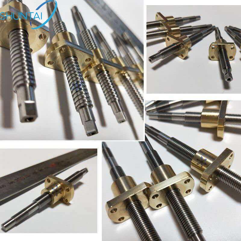
When you need a reliable, budget-friendly component to convert rotary motion into linear movement for your machinery, trapezoidal lead screws stand out as a classic choice. Our CNC machined TR32 trapezoidal threaded screw paired with bronze nuts delivers stable force transmission, ideal for low-speed, light-load industrial automation projects.Trapezoidal lead screws consist of a threaded shaft and matching trapezoid-profile nuts. The symmetrical isosceles trapezoid thread cross-section enables the nut to slide axially along the screw as rotation occurs, creating smooth linear displacement without complex rolling structures. Unlike ball screws that rely on circulating steel balls, trapezoidal screws operate via direct sliding contact between the shaft and nut.Key Specs of Our TR32 Trapezoidal Screw AssemblyOur Shuntai TR32 trapezoidal screw assemblies are built for consistent performance, with clear customizable parameters to match your equipment demands:Parameter Details Product Name Trapezoidal Lead Screw (TR32 32mm Series) Brand Shuntai Raw Materials GCr15 bearing steel for screw shaft; Bronze / Brass for matching nuts Production Process Rolled thread & precision ground thread options Core Advantage Extended service life, wear-resistant bronze nut Lead Time 7-day fast production for standard sizes Shipping Port Shanghai, flexible global sea & air freight support 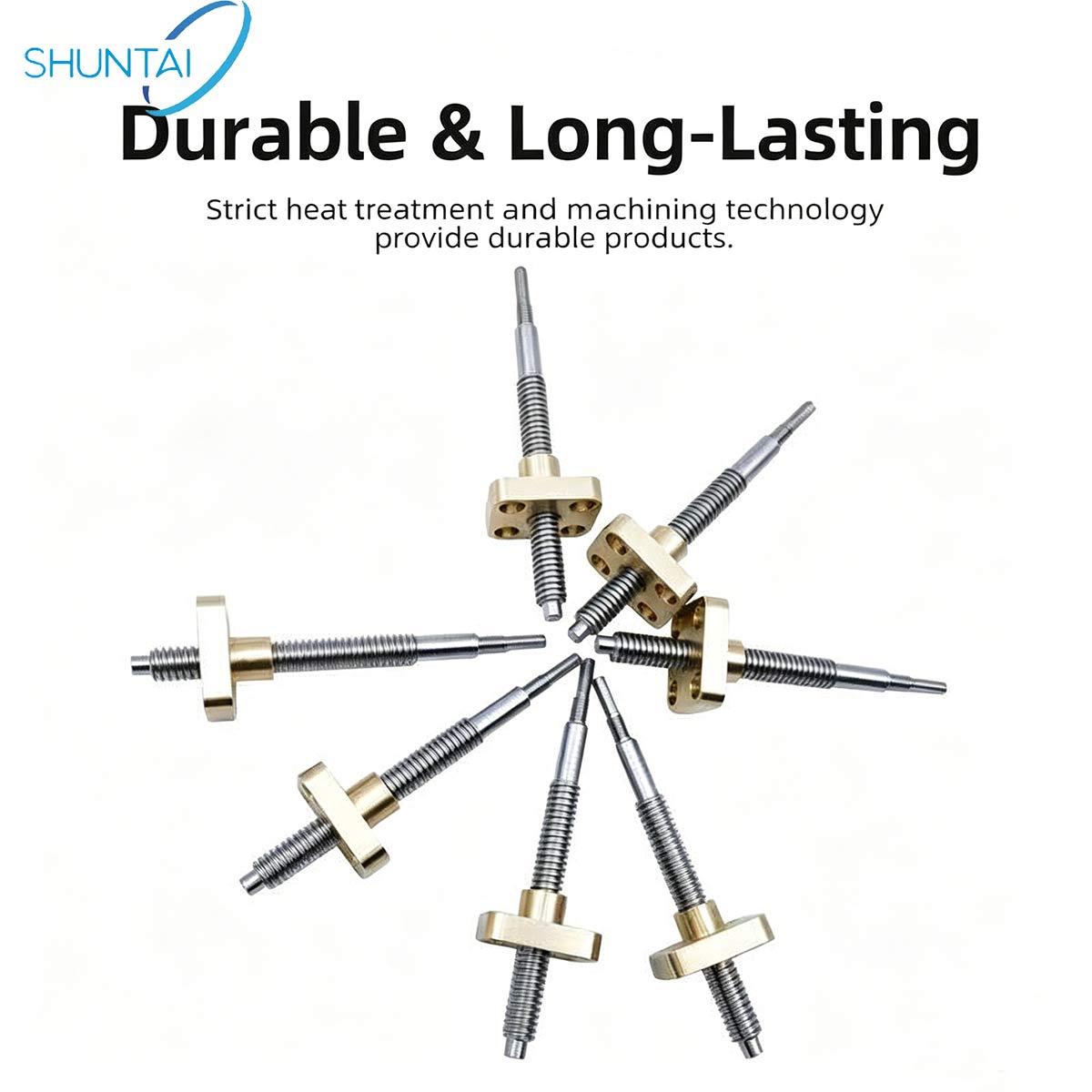
Pros & Cons of Trapezoidal Lead Screws (Honest Comparison to Ball Screws)
We share transparent performance characteristics to help buyers select the right linear motion part for their use case:
Main Advantages
- 1.Low manufacturing & procurement cost
Trapezoidal screws feature simplified machining workflows, making them far more affordable than precision ball screws. Perfect for small-batch machinery, DIY automation, conveyor systems, and low-budget equipment builds.
- 2.Simple, low-maintenance structure
No circulating ball components mean fewer fragile parts to inspect or replace. Bronze nuts naturally resist friction wear, cutting down long-term upkeep costs for your production line.
- 3.Self-locking capability (standard trapezoid thread)
Most trapezoidal thread designs offer built-in self-locking, which holds loads securely without extra braking parts — a valuable feature for lifting, positioning frames and adjustment stations.
Performance Limitations (For Application Reference)
- 1.Lower transmission efficiency
Sliding friction between steel screw and bronze nut creates more resistance than ball screw rolling contact, so trapezoidal screws are not recommended for high-speed continuous operation.
- 2.Limited heavy-load capacity
Sliding contact cannot support extreme heavy loads. Choose this series only for light to medium load working scenarios.
- 3.Moderate positioning accuracy
Backlash and repositioning error are more noticeable compared to ground ball screws. This product is not suited for ultra-precise measuring or high-tolerance machining equipment.
- Common Industrial Applications for TR32 Trapezoidal Screws
-
Thanks to their balanced cost and functionality, our 32mm TR32 trapezoidal lead screws are widely adopted across dozens of industries:
- • Light-duty automation assembly lines
- • Conveyor belt height adjustment mechanisms
- • Small CNC machine auxiliary adjustment axes
- • Medical equipment linear adjustment frames
- • Printing & packaging machinery
- • DIY robotic linear slides
- • Furniture lifting & height-adjustment devices
- For any project requiring basic linear motion, steady force transfer, and controlled production expenses, the TR32 trapezoidal screw kit with brass nut is a practical alternative to expensive precision ball screw sets.
- Why Choose Shuntai TR32 Trapezoidal Lead Screws?
- 1.Dual machining options: Choose rolled screws for cost savings or precision ground screws for smoother running performance.
- 2.Wear-resistant bronze matching nuts: Bronze material greatly reduces shaft abrasion and extends the full assembly service life.
- 3.Fast 7-day turnaround on standard TR32 sizes, with custom length, thread pitch, and end machining available on request.
- 4.Global shipping support from Shanghai port, with flexible logistics solutions for wholesale machinery parts buyers.
- 5.Full technical support: Our engineering team can provide dimension drawings and parameter consultation to match your machine design requirements.
- Get Custom TR32 Trapezoidal Screw Solutions Today
-
If you’re sourcing reliable trapezoidal lead screws for your automation equipment, conveyor systems or custom machinery builds, our Shuntai TR32 series balances durability and cost efficiency perfectly.Click our consultation button to send your dimensional drawings, load speed requirements, and quantity demands. Our sales team will reply quickly with detailed quotations and technical recommendations tailored to your project.
Trapezoidal Lead Screws Cost-Effective Linear Motion Solution for Your Automation Projects
Looking for a reliable, budget-friendly linear motion transmission component for your machinery, 3D printer or lifting platform? Trapezoidal lead screws are the ideal choice for low-to-medium load, low-speed automation applications.Unlike ball screws with complex internal circulation structures, trapezoidal lead screws feature simple T-shaped thread matching brass nuts, easily converting rotary motion into smooth linear movement. At Shuntai, we supply fully customizable trapezoidal lead screws with brass nuts, built for long service life and stable daily operation.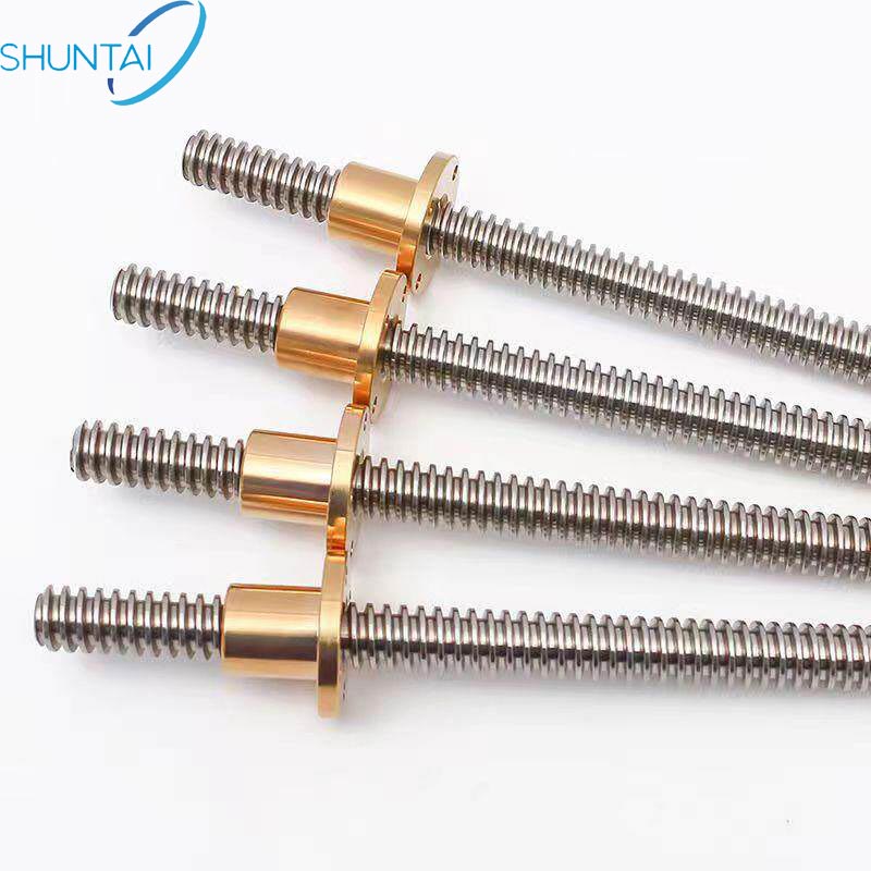 Core Specifications of Our Trapezoidal Lead ScrewsWe offer a full range of shaft diameters to match diverse equipment demands:
10mm, 12mm, 16mm, 20mm, 22mm, 24mm, 25mm, 28mm, 30mm, 36mmItem Details Product Name Trapezoidal Lead Screw with Bronze Nut Thread Type Trapezoidal (T-thread) Brand Shuntai Raw Material GCr15 bearing steel, carbon steel, bronze/brass nuts Manufacturing Process Rolled thread screws, ground precision screws Main Advantage Extended service life, stable transmission Lead Time 7 working days Shipment Port Shanghai, China
Our screws are available in two production standards: rolled lead screws for cost-sensitive general use, and ground lead screws for scenarios requiring better dimensional consistency. The matching brass nuts deliver good self-lubricating performance, reducing wear during repeated reciprocating movement.
How Trapezoidal Lead Screws WorkA complete trapezoidal screw drive system contains two core parts: a threaded screw shaft and a mating trapezoidal nut.
The trapezoidal thread features parallel spiral flanks. When the shaft rotates, torque transfers to the nut, pushing the nut to travel linearly along the screw axis.We provide nuts in multiple styles: standard flange brass nuts, black coated anti-rust nuts, and spring preloaded nuts to eliminate backlash for slightly higher precision assembly.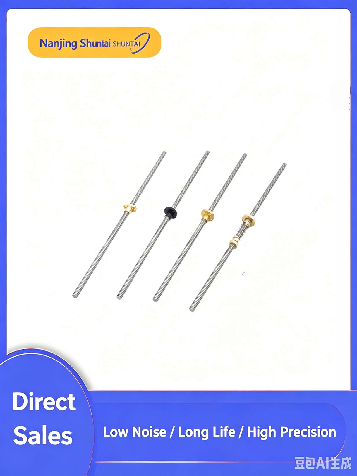 Main Advantages of Trapezoidal Lead Screws
1.Lower Production CostCompared to ball screws with circulating ball channels, trapezoidal lead screws have simpler processing steps, cutting down your procurement budget significantly for medium-load projects.2.Simple & Stable Mechanical Structure
No delicate rolling ball components inside. The solid screw-bronze nut pairing resists shock and dust, making maintenance straightforward for factory equipment.3.Strong Self-Locking Performance
Trapezoidal thread geometry creates natural self-locking when power cuts off. This is critical for lifting platforms, vertical 3D printer axes and vertical automation slides to prevent accidental sliding.
4.Wide Material Selection for Customization
Screw shafts use wear-resistant GCr15 bearing steel or regular carbon steel; brass/bronze nuts offer inherent lubricity without frequent heavy oiling.Typical Application Scenarios
Trapezoidal lead screws shine in low-speed, medium-load linear motion equipment, widely adopted across global industries:-
CNC machine auxiliary axes
-
Desktop & industrial 3D printers
-
Vertical lifting platforms & lifting tables
-
General automation assembly equipment
-
Medical linear adjustment devices
-
Small packaging machinery
Limitations to Consider Before Selection
For ultra-high speed or ultra-high precision positioning tasks, ball screws perform better. Trapezoidal lead screws have higher friction and lower transmission efficiency, so they work best for slow, intermittent operation instead of continuous high-speed cycling.
How to Pick the Right Trapezoidal Lead Screw for Your Project
When placing your order, evaluate 4 core factors to avoid mismatched parts: - 1.Load Weight: Confirm your maximum moving load to select proper shaft diameter (10mm for light loads, 36mm for heavy medium loads)
- 2.Running Speed: Stick to trapezoidal screws if your linear speed stays low; opt for ball screws for fast continuous travel
- 3.Position Accuracy: Ground trapezoidal screws for tighter tolerance needs, rolled screws for standard positioning
- 4.Project Budget: Trapezoidal screws offer far better cost performance than precision ball screws
Micro SD Card Speed Class Guide Class 10 to U3 to V30 (2026)
Selecting the right Micro SD card for your device requires understanding a confusing array of speed class labels—Class 10, U1, U3, V10, V30, A1, A2, and more. This guide explains each speed class, what it means for real-world performance, and how to choose the right Micro SD card socket connector for your application.
Why Micro SD Speed Classes Matter
The speed class on a Micro SD card indicates its minimum sequential write speed—the guaranteed floor performance, not the peak. This distinction is critical because a card labeled "100 MB/s read" may only sustain 10 MB/s writes, which could cause dropped frames in video recording or data loss in IoT logging applications.
Micro SD Speed Class Comparison Table
Speed Class Symbol Min Sequential Write Typical Use Case SD Specification Class 2 C2 2 MB/s Standard definition video SD 2.0 Class 4 C4 4 MB/s SD video, basic photo SD 2.0 Class 6 C6 6 MB/s HD video (720p) SD 2.0 Class 10 C10 10 MB/s Full HD video (1080p) SD 3.0 U1 (UHS-I) U1 10 MB/s Full HD video, general use SD 3.01 U3 (UHS-I) U3 30 MB/s 4K video (UHD) SD 4.0 V10 (Video) V10 10 MB/s Full HD video SD 5.0 V30 (Video) V30 30 MB/s 4K UHD video SD 5.0 V60 (Video) V60 60 MB/s 8K video, high-bitrate 4K SD 6.0 V90 (Video) V90 90 MB/s 8K video, professional cinema SD 6.0 Understanding UHS Bus Interfaces
Speed classes are only half the story. The bus interface determines the maximum theoretical throughput between the card and the host:
Bus Interface Max Transfer Rate Voltage SD Spec Version Default Speed 25 MB/s 3.3V SD 1.0 High Speed 50 MB/s 3.3V SD 2.0 UHS-I 104 MB/s 1.8V (switchable) SD 3.0 UHS-II 312 MB/s 1.8V + extra pins SD 4.0 UHS-III 624 MB/s 1.8V + extra pins SD 6.0 SD Express (PCIe) 985 MB/s 1.8V + PCIe/NVMe SD 7.0/8.0 ⚠ Important: A UHS-II card in a UHS-I slot will only operate at UHS-I speeds (104 MB/s max). The host device and card socket must both support the target bus interface.Application Performance Class: A1 vs A2
For devices that run applications directly from the Micro SD card (Android Adoptable Storage, IoT edge computing), the Application Performance Class matters more than sequential speed:
Class Min Random IOPS (Read) Min Random IOPS (Write) Min Sustained Write Target Use A1 1,500 500 10 MB/s Basic app launch A2 4,000 2,000 30 MB/s Multi-app, caching A2 cards require host support for command queuing and cache management to achieve their rated performance. In a host that does not support these features, an A2 card may perform no better than an A1 card.
Micro SD Card Socket Connector Requirements by Speed Class
The speed class of the Micro SD card your device uses directly impacts the connector requirements:
Target Speed Bus Interface Socket Pin Count Key Socket Feature VITALCONN Example Up to 50 MB/s High Speed 8-pin Standard push-push/pull VTC102013832E1 Up to 104 MB/s UHS-I 8-pin UHS-I compatible contacts VTC102013832E2 Up to 312 MB/s UHS-II 17-pin Extra row of contacts VTC402016832E1 Up to 985 MB/s SD Express 2-row/NVMe PCIe/NVMe signal integrity VTC402018832E1 Micro SD Socket Height: Why It Matters
In portable devices, the Z-height (profile height) of the Micro SD socket is often the most constrained dimension:
- H1.13~H1.25 mm — Ultra-slim smartphones, smartwatches, medical wearables
- H1.8~H2.2 mm — Tablets, thin laptops, portable monitors
- H2.5~H3.0 mm — Industrial devices, IoT gateways, automotive
💡 Tip: VITALCONN's C102316832E1 is a standout example: a Micro SD push-push socket with H1.25 mm profile, pin-to-pin compatible with JAE SF72S006VBDR2500, offered at 30% lower cost with 2–4 week lead time versus 12–24 weeks.How to Choose the Right Micro SD Card and Socket
Follow this decision process:
- Determine the minimum sustained write speed your application requires (video bitrate, data logging rate)
- Select the appropriate speed class (C10 for basic, U3/V30 for 4K, V60+ for 8K)
- Determine the bus interface needed (UHS-I for ≤104 MB/s, UHS-II for ≤312 MB/s, SD Express for ≤985 MB/s)
- Choose a socket connector that supports the required bus interface and fits your Z-height budget
- Verify the socket's insertion cycle rating (5,000+ for consumer, 10,000+ for industrial)
Frequently Asked Questions (FAQ)
Is Class 10 the same as U1?Both Class 10 and U1 guarantee a minimum sequential write speed of 10 MB/s. However, U1 is tested under UHS-I bus conditions and may have different performance characteristics. For new designs, UHS-I (U1/U3) is preferred over the older Class 10 designation.Can I use a UHS-II card in a UHS-I socket?Yes, UHS-II cards are backward compatible with UHS-I hosts. However, the card will only operate at UHS-I speeds (up to 104 MB/s). To achieve UHS-II speeds, both the card and the host socket must support the UHS-II bus interface with the additional pin row.What is the fastest Micro SD card speed available in 2026?SD Express (SD 7.0/8.0) cards using PCIe/NVMe interface can achieve up to 985 MB/s sequential read speeds. These require specialized SD Express card sockets with PCIe signal routing. VITALCONN offers SD 7.0/8.0 compatible card sockets for next-generation devices.Ready to Find the Right Micro SD Card Socket?Explore VITALCONN's full range of Micro SD card sockets—from H1.25 mm ultra-slim push-push to UHS-II/SD Express models—or request free samples for your next project.Explore Micro SD Sockets Request Free SamplesNano SIM vs Micro SIM vs Standard SIM Complete Comparison Guide (2026)
Choosing the right SIM card form factor is one of the first decisions engineers face when designing connected devices. Whether you are building a slim smartphone, a compact IoT sensor, or an industrial gateway, understanding the differences between Standard SIM, Micro SIM, and Nano SIM is critical for selecting the correct SIM card socket connector. This guide provides a detailed comparison to help you make an informed design choice.
What Are the Three SIM Card Sizes?
SIM cards come in three standardized physical sizes defined by ETSI and ISO/IEC 7810. All three carry identical electrical contacts and functionally perform the same — the only difference is the physical form factor.
SIM Type Dimensions (mm) Area (mm²) Thickness (mm) Introduced ISO Standard Standard SIM (1FF) 85.6 × 53.98 4,621 0.76 1991 ISO 7810 ID-1 Micro SIM (3FF) 15.0 × 12.0 180 0.76 2003 ETSI TS 102 221 Nano SIM (4FF) 12.3 × 8.8 108.24 0.67 2012 ETSI TS 102 221 V11.0.0 The progression from Standard to Micro to Nano SIM has been driven entirely by the demand for smaller, thinner devices. A Nano SIM is approximately 97.7% smaller in area than a Standard SIM, freeing up valuable PCB real estate for other components.
Nano SIM vs Micro SIM vs Standard SIM: Key Differences at a Glance
Feature Standard SIM Micro SIM Nano SIM Dimensions 85.6×53.98 mm 15×12 mm 12.3×8.8 mm Contact pad size Full card Same as Standard Slightly reduced Electrical function Identical Identical Identical Typical use today Legacy devices Older smartphones, M2M Modern phones, IoT, wearables PCB footprint Very large Compact Ultra-compact Socket connector height H3.0~5.0 mm H1.5~3.0 mm H1.13~2.5 mm Adapter available N/A Yes (to Standard) Yes (to Micro/Standard) When Should You Use a Nano SIM?
The Nano SIM is the dominant form factor for modern designs. You should choose Nano SIM when:
- Your device has strict space constraints — smartphones, wearables, medical devices
- You need the lowest-profile SIM socket — as thin as 1.13 mm for push-push type
- Your target market uses current-generation mobile networks — 4G/5G
- You want forward compatibility — with the latest carrier SIM cards
💡 Tip: VITALCONN offers Nano SIM card sockets as thin as 1.13 mm in a push-push configuration — among the slimmest available in the industry. These sockets are ideal for portable devices where every millimeter of Z-height matters.When Should You Use a Micro SIM?
While Nano SIM has largely replaced Micro SIM in consumer devices, there are still valid use cases:
- Legacy product lines that have not yet migrated to Nano SIM
- Industrial M2M modules that ship with Micro SIM form factor
- Automotive telematics systems designed before 2018
- Cost-sensitive designs where Micro SIM sockets are marginally cheaper
Is Standard SIM Still Relevant?
Standard SIM is rarely used in new product designs. However, it still appears in:
- Industrial equipment with legacy SIM readers
- Banking and payment terminals (Smart Card form factor)
- Older networking and telecom hardware
⚠ Important: For new designs, VITALCONN recommends Nano SIM as the default choice unless legacy compatibility is a specific requirement.SIM Card Socket Connector Selection Guide
Selecting the right SIM card socket connector involves more than just matching the SIM form factor. Key parameters include:
Mounting Type
- Push-Push: User inserts and ejects the card with a spring mechanism. Best for consumer devices where the end user swaps SIM cards.
- Push-Pull: User pulls the card out manually. Common in industrial devices where the SIM is inserted once and rarely removed.
- Hinged/Trap: Card slides under a hinged cover. Provides the most secure retention for high-vibration environments.
Profile Height
Socket height is often the most critical dimension in slim device design:
Application Recommended Height VITALCONN Example Ultra-slim phones/wearables H1.13~1.5 mm VTC102016832E1 (Push-Push, H1.25mm) Tablets/laptops H1.5~2.2 mm VTC402013832E1 (Push-Push, H1.65mm) IoT gateways/routers H2.0~3.0 mm VTC102016832E2 (Push-Push, H2.5mm) Industrial equipment H2.5~5.0 mm VTC102016838E1 (Push-Pull, H3.0mm) Environmental Ratings
For applications exposed to harsh conditions, consider sockets with operating temperature ranges of -40°C to +85°C and compliance with EIA-364 environmental testing standards. VITALCONN SIM card sockets are tested per EIA-364 for thermal shock, salt spray corrosion, temperature cycling, and solderability (245±5°C).
SIM Card Socket Cross-Reference: Replacing Molex and JAE Parts
Many designs originally specified Molex or JAE SIM card sockets. VITALCONN provides pin-to-pin compatible replacements with shorter lead times and competitive pricing:
VITALCONN P/N Competitor P/N Brand Description VTC102016832E1 SF72S006VBDR2500 JAE Nano SIM Push-Push H1.25mm VTC402013832E1 5039600695 Molex Micro SIM Push-Push H1.65mm VTC402013832E2 5027740891 Molex Micro SIM Push-Push H2.5mm VTC102016832E2 105162-0001 Molex Nano SIM Push-Push H2.5mm These cross-reference options offer 30–40% cost savings and 2–4 week lead times versus 12–24 weeks for the original parts.
Frequently Asked Questions (FAQ)
Can I cut a Standard SIM into a Nano SIM?Technically, yes — SIM card cutters exist that trim a Standard or Micro SIM down to Nano SIM size. However, this is not recommended for production devices because the cut edges can damage the socket contacts, and the reduced thickness of a Nano SIM (0.67 mm vs 0.76 mm) may cause contact reliability issues.Are Nano SIM and Micro SIM electrically identical?Yes. All three SIM sizes use the same 8-contact ISO/IEC 7816 interface. The electrical specifications are identical — the only differences are the physical dimensions of the plastic carrier.What is the minimum profile height for a Nano SIM socket?The thinnest Nano SIM sockets available are approximately 1.13 mm in profile height. VITALCONN offers push-push Nano SIM sockets starting from H1.25 mm, suitable for ultra-slim device designs.How many insertion cycles can a SIM card socket handle?Quality SIM card sockets are rated for 5,000 to 10,000 insertion cycles. VITALCONN SIM sockets are tested to 5,000 cycles minimum per EIA-364 standards.Ready to Find the Right SIM Card Socket?Explore VITALCONN's full range of SIM card sockets or request free samples for your next project.Explore SIM Card Sockets Request Free SamplesPress-Fit vs Solder PCB Assembly Guide for Connector Mounting (2026)
When mounting connectors on a printed circuit board, engineers have two primary options: press-fit (also called compliant pin or press-in) and traditional solder mounting. While solder has been the default for decades, press-fit technology has become the preferred choice for high-reliability applications—especially in data center, telecommunications, and automotive electronics. This guide explains the differences, advantages, and selection criteria for each method.
What Is Press-Fit Mounting?
Press-fit mounting uses specially designed compliant pins that deform elastically when pressed into plated through-holes on the PCB. The pins create a gas-tight, cold-welded connection without any solder. The compliant section of the pin is typically shaped like an eye, hourglass, or multiple contact bands that maintain constant outward force against the through-hole barrel.
What Is Solder Mounting?
Solder mounting uses through-hole soldering (wave soldering or selective soldering) to create a metallurgical bond between the connector pins and the PCB. The solder joint provides both the electrical connection and mechanical retention. Solder mounting has been the industry standard for decades and is still widely used for cost-sensitive applications.
Press-Fit vs Solder: Head-to-Head Comparison
Parameter Press-Fit Solder Connection type Cold-welded gas-tight Metallurgical solder joint Process temperature Room temperature (no heat) 240–260°C (reflow/wave) FIT (Failures in Time) 0.1–1 per billion hours 3–30 per billion hours Reliability 10–30× higher than solder Baseline Thermal cycling resistance Excellent (flexible pin compensates) Moderate (solder cracks possible) Assembly process Press-in only (one step) Insert → wave solder → inspect (multi-step) Rework capability Not reworkable (pin deformation) Reworkable with desoldering tools PCB design Requires specific hole sizes (0.45–0.55mm) More flexible hole size range Initial cost Slightly higher per connector Lower per connector Total assembly cost Lower (fewer process steps) Higher (soldering + inspection) RoHS compliance Inherently lead-free Requires lead-free solder alloys Why Press-Fit Is 10–30× More Reliable Than Solder
The dramatic reliability difference comes down to the physics of each connection:
Press-fit pins maintain a constant spring force against the through-hole barrel, creating a gas-tight connection that resists oxidation and corrosion. The compliant pin flexes with thermal expansion and contraction, preventing stress accumulation.
Solder joints, by contrast, are rigid. During thermal cycling, the different coefficients of thermal expansion (CTE) between the connector, solder, and PCB create mechanical stress. Over thousands of cycles, this stress can cause solder joint cracks—the most common failure mode in through-hole soldered connectors.
Real-World FIT Value Comparison
Metric Press-Fit Solder Improvement Factor FIT value (typical) 0.5 8.0 16× Thermal cycle life (-40°C to +125°C) >2,000 cycles 500–1,000 cycles 2–4× Vibration resistance Excellent Good Significant Drop/shock resistance Excellent Moderate Significant When Should You Choose Press-Fit?
Press-fit is the recommended choice when:
- Your application requires high reliability (data center, telecom, automotive, aerospace)
- The product will experience significant thermal cycling (outdoor equipment, industrial)
- You want to eliminate the wave soldering step and reduce assembly cost
- You need to meet stringent DPPM targets (<300 PPM)
- Your design uses high-density, multi-port connectors (SFP cages, DIN connectors)
When Is Solder Still Appropriate?
Solder mounting remains a valid choice when:
- The connector is low-pin-count and cost is the primary driver
- Your PCB assembly line does not have press-fit insertion equipment
- Rework or field repair capability is required
- The application has minimal thermal cycling and vibration exposure
SFP Cage: The Strongest Case for Press-Fit
SFP cage connectors are perhaps the most compelling application for press-fit mounting. Here's why:
- Pin count: High port density—Multi-port SFP cages (2×1 to 2×8) have 40–80+ through-hole pins per cage. A single solder defect on any pin can cause a port failure.
- Mission-critical: SFP cages are used in switches and servers that must operate 24/7 for 5–10+ years. Press-fit eliminates solder joint fatigue as a failure mode.
- Hot-plug stress: SFP modules are hot-pluggable, creating repeated mechanical stress on the cage. Press-fit's superior vibration resistance is essential.
💡 Tip: VITALCONN offers 89 press-fit SFP cage models covering SFP, SFP+, SFP28, QSFP+, QSFP28, QSFP-DD, and OSFP form factors—the broadest selection in the industry.Press-Fit SFP Cage Cross-Reference: Replacing TE and Molex
VITALCONN provides press-fit SFP cage replacements that are pin-to-pin compatible with TE Connectivity and Molex parts:
VITALCONN P/N Competitor P/N Brand Form Factor Ports S2N3104800NA4 2007215-1 TE SFP+ 1×1 S2N3122055NA4 2149730-1 TE SFP+ w/ EMI 1×1 S2N32H0206NA4 2227303-2 TE QSFP28 2×6 S2N3400556NA4 74441-0001 Molex SFP+ 1×1 S1N3A23000CA4 747548220 Molex SFP28 w/ Heatsink 1×1 All VITALCONN press-fit SFP cages offer 30–40% cost savings over TE/Molex equivalents with 2–4 week lead times.
How to Specify Press-Fit Connectors in Your Design
When designing with press-fit connectors, pay attention to these PCB requirements:
- Hole size: Follow the connector manufacturer's recommended hole size and tolerance (typically ±0.05 mm)
- Plating: Ensure adequate copper thickness (≥25 μm) in the through-hole barrels
- Clearance: Maintain minimum 2 mm clearance around press-fit holes for insertion tool access
- Insertion force: Use press-fit insertion tools with controlled force (typically 50–150 N per pin)
Frequently Asked Questions (FAQ)
Can press-fit pins be reworked if damaged?Press-fit pins cannot be re-soldered or re-inserted once the compliant section has been deformed. If a press-fit connection fails, the typical repair is to replace the entire connector or use a modified solder repair process. This is why press-fit is best suited for applications where field rework is not expected.Does press-fit work with double-sided PCBs?Yes. Press-fit connections are compatible with multi-layer PCBs. The key requirement is that the through-hole plating meets the connector manufacturer's specifications for barrel thickness and surface finish (typically HASL, ENIG, or OSP).What is the typical insertion force for press-fit SFP cages?Press-fit insertion force depends on the number of pins. A typical 1×1 SFP cage requires approximately 50–80 N of insertion force. Multi-port cages (2×4, 2×6) may require 200–400 N. Always use the manufacturer's recommended insertion tool to ensure uniform pin deformation.Ready to Upgrade to Press-Fit SFP Cages?Explore VITALCONN's 89 press-fit SFP cage models—pin-to-pin compatible with TE and Molex, 30–40% cost savings, 2–4 week lead times—or request free samples for your next project.Explore Press-Fit SFP Cages Request Free SamplesPush-Push vs Push-Pull Card Socket Which One Should You Choose? (2026)
Card socket connectors come in two primary ejection mechanisms: push-push and push-pull. While both serve the same fundamental purpose—holding a SIM, Micro SD, or SD card securely in place—their user experience, reliability, and mechanical design differ significantly. This guide explains the differences and helps you select the right mechanism for your device.
What Is a Push-Push Card Socket?
A push-push card socket uses a spring-loaded mechanism. The user inserts the card with a push, and a latch locks it in place. To eject, the user pushes the card again, which releases the latch and the spring pops the card out partially for easy removal.
This mechanism is familiar to most consumers—it's the same system used in camera SD card slots and smartphone SIM trays.
What Is a Push-Pull Card Socket?
A push-pull card socket has no ejection mechanism. The user inserts the card by pushing it in, and removes it by pulling it out directly. The card is held in place by friction from the contact beams inside the socket.
This simpler design is common in industrial and M2M (machine-to-machine) applications where the card is inserted once and rarely removed.
Push-Push vs Push-Pull: Detailed Comparison
Feature Push-Push Push-Pull Insertion Push in (auto-latch) Push in (friction hold) Ejection Push again (spring ejects card) Pull out manually User experience Intuitive, one-handed operation Requires grip on card edge Card retention Mechanical latch (very secure) Friction only (less secure) Vibration resistance Excellent (latch prevents ejection) Moderate (card can creep out) Profile height Typically taller (spring mechanism) Typically shorter (simpler) Part count More internal components Fewer internal components Cost Slightly higher Slightly lower Typical insertion cycles 5,000–10,000 5,000–10,000 Best for Consumer devices, frequent card swap Industrial, set-and-forget When Should You Choose Push-Push?
Push-push is the right choice when:
- End users will swap cards regularly (smartphones, cameras, consumer electronics)
- One-handed card insertion/ejection is important for the user experience
- The device will be exposed to vibration or shock (automotive, portable devices)
- You need the card to stay securely locked in place without any risk of accidental ejection
- The card slot is recessed, making it difficult to grip the card for pull-out
When Should You Choose Push-Pull?
Push-pull is the right choice when:
- The card is inserted once during manufacturing and rarely or never removed (IoT devices, industrial gateways)
- You need the lowest possible profile height (push-pull sockets can be as thin as 1.13 mm)
- Cost optimization is a primary concern (fewer internal components)
- The device is in a controlled environment with minimal vibration
- Space constraints make the push-push spring mechanism too tall
Profile Height Comparison: Which Mechanism Is Slimmer?
A common misconception is that push-pull is always slimmer than push-push. In reality, the height difference depends on the specific model:
Card Type Mechanism Height Range Thinnest Available Nano SIM Push-Push H1.25~2.5 mm H1.25 mm Nano SIM Push-Pull H1.13~2.0 mm H1.13 mm Micro SIM Push-Push H1.65~3.0 mm H1.65 mm Micro SD Push-Push H1.25~2.8 mm H1.25 mm Micro SD Push-Pull H1.13~2.5 mm H1.13 mm SD Card Push-Push H2.5~5.0 mm H2.5 mm For ultra-slim designs (H<1.5 mm), push-pull is typically the only option. For heights above 1.5 mm, push-push is available and often preferred for its superior retention.
⚠️ Important: Push-pull sockets rated below H1.25 mm are exclusively friction-hold designs. If your application involves any vibration, verify the retention force specification—friction-only retention can allow the card to creep out under sustained shock.Card Socket Cross-Reference: VITALCONN Replacements for Molex and JAE
VITALCONN offers push-push and push-pull card socket replacements compatible with Molex, JAE, and other major brands:
VITALCONN P/N Competitor P/N Brand Card Type Mechanism Height VTC102016832E1 SF72S006VBDR2500 JAE Nano SIM Push-Push H1.25 mm VTC102016832E2 105162-0001 Molex Nano SIM Push-Push H2.5 mm VTC402013832E1 5039600695 Molex Micro SIM Push-Push H1.65 mm C102316832E1 ST11S008V4HR2000 JAE Micro SD Push-Push H1.25 mm 💡 Tip: The C102316832E1 is VITALCONN's flagship Micro SD push-push socket: an ultra-thin 1.25 mm profile design that is pin-to-pin compatible with JAE ST11S008V4HR2000, priced at approximately 70% of the JAE part with 2–4 week lead time.Frequently Asked Questions (FAQ)
Is push-push more reliable than push-pull?Both mechanisms can achieve 5,000+ insertion cycles. However, push-push provides more secure card retention thanks to the mechanical latch. In high-vibration environments, push-push is clearly superior because the latch prevents the card from creeping out under sustained vibration.Can a push-pull socket be used in a consumer device?It can, but it's not ideal. Consumer users expect the push-push ejection experience. A push-pull socket in a consumer device may lead to user frustration, especially if the card is difficult to grip for removal. Push-pull is better suited for industrial applications where the card is inserted once.What is the thinnest Micro SD socket available?The thinnest Micro SD sockets are approximately 1.13 mm in profile height. These are push-pull type. The thinnest push-push Micro SD sockets are approximately 1.25 mm. VITALCONN offers both types across its card socket product line.Ready to Find the Right Card Socket?Explore VITALCONN's full range of push-push and push-pull card sockets—pin-to-pin compatible with Molex and JAE, 30% cost savings, 2–4 week lead times—or request free samples for your next project.Explore Card Sockets Request Free SamplesSFP Cage EMI Shielding Why It Matters for 400G and 800G Data Centers (2026)
As data center speeds scale from 100G to 400G and 800G, electromagnetic interference (EMI) shielding in SFP cage connectors becomes a make-or-break design consideration. At 25 Gbps per lane and above, even minor EMI leakage can degrade signal integrity, cause bit errors, and result in compliance failures. This guide explains why EMI shielding matters, how it works, and what to look for when selecting SFP cages for high-speed applications.
What Is EMI and Why Does It Matter in SFP Cages?
Electromagnetic interference (EMI) is unwanted electromagnetic energy that disrupts the normal operation of electronic circuits. In SFP cage assemblies, EMI originates from two primary sources:
- Radiated emissions: High-speed differential signals (25G, 50G, 100G per lane) radiate electromagnetic energy through the cage openings
- Crosstalk: Adjacent ports in multi-port cage configurations can couple noise between channels
At 10Gbps and below, the impact of EMI leakage through SFP cages is manageable. But at 25Gbps per lane (QSFP28 and above), the signal wavelengths are short enough that cage openings become efficient antennas, making robust EMI shielding essential.
How SFP Cage EMI Shielding Works
Effective SFP cage EMI shielding creates a continuous Faraday cage around the transceiver module. Key design elements include:
1. EMI Gaskets (Spring Fingers)
Beryllium copper (BeCu) EMI gaskets and spring fingers make 360° contact between the cage body and the transceiver module's metal housing. This continuous grounding path prevents EMI from leaking through gaps between the module and cage.
VITALCONN SFP cages use BeCu spring fingers that achieve crosstalk isolation below -40 dB at 10 GHz, among the best performance available in the industry.
2. Cage Body Design
The cage body itself acts as the primary EMI shield. Critical design factors include:
- Material thickness — thicker walls provide better shielding but increase cost
- Seam design — overlapping seams minimize leakage
- Port divider walls — metal barriers between adjacent ports reduce crosstalk
3. PCB-Level Grounding
The EMI shield is only as good as its grounding connection to the PCB. Press-fit cages inherently provide better grounding than solder cages because:
- Each press-fit pin creates a gas-tight, low-impedance ground connection
- Press-fit pins maintain consistent contact force over the product lifetime
- Multiple ground pins distribute ground current evenly, reducing ground plane noise
EMI Shielding Requirements by Data Rate
Data Rate Lanes Form Factor EMI Shielding Level Cage Design Considerations 1G 1 SFP Basic Simple cage, minimal gasketing 10G 1 SFP+ Moderate EMI gasket recommended 25G 1 SFP28 High 360° BeCu gasket required 40G 4×10G QSFP+ High Port dividers + gaskets 100G 4×25G QSFP28 Very High Full shielding + port dividers 400G 8×50G QSFP-DD Critical Full shielding + dividers + thermal 800G 8×100G OSFP Critical Full shielding + dividers + active cooling Why EMI Shielding Becomes Critical at 400G/800G
At 400G (QSFP-DD) and 800G (OSFP), the EMI challenge intensifies for three reasons:
- Higher per-lane speed: Each lane carries 50G or 100G, producing proportionally stronger radiated emissions
- More lanes = more openings: 8-lane cages have more internal gaps and seam paths where EMI can leak
- Thermal-EMI trade-off: The heatsink required to cool 400G/800G modules adds thermal design complexity that must not compromise EMI integrity
VITALCONN SFP Cage EMI Shielding Solutions
VITALCONN SFP cages are engineered for the highest EMI shielding performance:
BeCu 360° EMI Gaskets
All VITALCONN SFP28, QSFP28, QSFP-DD, and OSFP cages feature beryllium copper spring fingers that provide continuous 360° grounding contact. Key performance metrics:
- Crosstalk isolation: <-40 dB at 10 GHz
- Contact resistance: <10 mΩ per finger
- Spring force: maintained over 10,000+ insertion cycles
💡 Tip: VITALCONN's BeCu spring fingers achieve the industry's best crosstalk isolation at <-40 dB, giving designers 5–10 dB of additional margin over competing solutions for compliance with FCC Part 15 and CISPR 32 emission limits.Integrated Port Dividers
Multi-port cages include metal port divider walls that isolate adjacent channels, preventing inter-port crosstalk in high-density switch designs.
Thermal-EMI Integrated Design
VITALCONN cages with integrated heatsinks use a top-vent design that provides both thermal airflow and EMI containment. The heatsink fins are electrically bonded to the cage body, maintaining shielding integrity while allowing convective cooling.
Measuring SFP Cage EMI Performance
When evaluating SFP cage EMI performance, look for these test results:
- Crosstalk: Near-end crosstalk (NEXT) at the target data rate
- Emissions: FCC Part 15 Class A (commercial) and Class B (residential)
- Signal integrity: Insertion loss and return loss through the cage assembly
VITALCONN provides EMI test data for all SFP cage models, enabling designers to validate compliance before committing to a design.
SFP Cage Cross-Reference for High-Speed Applications
VITALCONN offers pin-to-pin SFP cage replacements optimized for EMI performance:
VITALCONN P/N Competitor P/N Brand Speed Ports EMI Feature S2N32H1000NA4 2291634-2 TE QSFP28 (100G) 2×1 BeCu gasket + divider S2N32H0206NA4 2227303-2 TE QSFP28 (100G) 2×6 Full EMI shield S1N3A23000CA4 747548220 Molex SFP28 (25G) 1×1 BeCu gasket + heatsink S2N3D23004BA4 1-2149490-5 TE QSFP-DD (400G) 1×1 Full EMI + thermal ⚠️ Important: At 400G (QSFP-DD) and 800G (OSFP), full EMI shielding is not optional. Multi-port cages without proper port dividers and 360° BeCu gaskets will fail FCC/CISPR emission compliance. Always verify EMI test data before finalizing your BOM.Frequently Asked Questions (FAQ)
Do I need EMI shielding for 10G SFP+ cages?EMI gaskets are recommended for 10G SFP+ cages, especially in multi-port configurations. While some 10G designs may work without gaskets in low-density setups, the cost of adding EMI shielding is minimal compared to the risk of EMI-related signal integrity issues.Can I add EMI shielding to an existing SFP cage design?EMI gaskets can sometimes be retrofitted, but the most effective approach is to select a cage designed with integrated EMI shielding from the start. Retrofit gaskets may not achieve 360° contact and can interfere with module insertion.How does heatsink design affect EMI shielding?A properly designed heatsink is electrically bonded to the cage body and does not compromise EMI shielding. However, poorly designed heatsinks with gaps or floating sections can create EMI leakage paths. VITALCONN's integrated heatsink designs maintain full EMI integrity while providing thermal management.Ready to Optimize Your EMI Shielding Design?Explore VITALCONN's full range of EMI-shielded SFP cages—pin-to-pin compatible with TE and Molex, 30–40% cost savings, 2–4 week lead times—or request free samples and EMI test data for your next project.Explore EMI SFP Cages Request Free SamplesSFP vs SFP+ vs SFP28 vs QSFP28 Complete Speed & Compatibility Guide (2026)
As data centers scale from 1G to 800G and beyond, understanding the differences between SFP form factors is essential for network engineers, hardware designers, and procurement teams. This guide explains each SFP variant—its speed, application, cage connector requirements, and how to choose the right one for your infrastructure.
What Is an SFP Transceiver?
SFP (Small Form-factor Pluggable) is a hot-pluggable transceiver interface standard used in networking equipment. It defines both the optical/electrical module and the cage connector that hosts it on the PCB. The SFP ecosystem has evolved through multiple generations, each delivering higher data rates while maintaining backward compatibility with earlier form factors.
SFP vs SFP+ vs SFP28 vs QSFP28: Speed Comparison Table
Form Factor Data Rate Lane Count Connector Type Cage Keying Typical Application SFP 1 Gbps 1 LC / RJ45 SFP Fast/Gigabit Ethernet, Fibre Channel SFP+ 10 Gbps 1 LC / RJ45 SFP (compatible) 10G Ethernet, 8G/16G FC SFP28 25 Gbps 1 LC / RJ45 SFP (compatible) 25G Ethernet, 32G FC QSFP+ 40 Gbps 4×10G MPO / LC QSFP 40G Ethernet, InfiniBand FDR QSFP28 100 Gbps 4×25G MPO / LC QSFP (compatible) 100G Ethernet, EDR InfiniBand QSFP-DD 200/400 Gbps 8×25/50G MPO-16 / LC QSFP-DD 400G Ethernet, AI data centers OSFP 200/400/800G 8×50/100G MPO-16 OSFP 800G Ethernet, next-gen AI Are SFP, SFP+, and SFP28 Backward Compatible?
Yes—this is one of the most important characteristics of the SFP ecosystem. The physical cage connector and electrical interface are designed for forward and backward compatibility:
- Downshift: An SFP module can be inserted into an SFP+ or SFP28 cage (operates at 1G)
- Upshift (limited): An SFP28 module can be inserted into an SFP+ cage (operates at 10G, not 25G)
- Same cage: The physical dimensions of SFP, SFP+, and SFP28 modules are identical (same cage footprint)
This backward compatibility means that the same SFP cage connector on your PCB can support 1G, 10G, or 25G modules, protecting your hardware investment across network upgrades.
What Is the Difference Between SFP+ and QSFP+?
The key difference is the number of channels:
- SFP+ provides a single 10G channel (1×10G). It uses a single TX/RX pair.
- QSFP+ provides four 10G channels (4×10G) for an aggregate 40G bandwidth. It uses four TX/RX pairs in a wider cage.
Physically, QSFP+ cages are wider than SFP+ cages (approximately 18.35 mm vs 13.8 mm port width) and use a different keying system. A QSFP+ cage cannot accept an SFP+ module and vice versa.
QSFP28 vs QSFP-DD: The Path to 400G and 800G
As AI workloads and cloud infrastructure demand ever-higher bandwidth, the industry has moved beyond QSFP28:
- QSFP-DD: QSFP-DD doubles the lane count from 4 to 8 while maintaining backward compatibility with QSFP28 modules. It supports 200G (8×25G) and 400G (8×50G).
- OSFP: OSFP provides a larger form factor with 8 electrical lanes, supporting up to 800G (8×100G). It is not backward compatible with QSFP cages.
For data center designers planning for 800G, OSFP is the future-proof choice. For those upgrading existing 100G infrastructure to 400G, QSFP-DD offers the best migration path.
SFP Cage Connector Selection: Press-Fit vs Solder
Beyond the transceiver module itself, the cage connector that mounts on the PCB is equally critical. Two primary mounting technologies are available:
Solder-Type Cages
- Lower initial tooling cost
- Requires wave soldering or selective soldering process
- Higher FIT (Failures In Time) values—typically 10–30× higher than press-fit
- Risk of solder joint cracks under thermal cycling
Press-Fit Cages
- No soldering required—cold-rolled compliant pins press into plated through-holes
- FIT values 10–30× lower than solder, significantly improving reliability
- Compatible with lead-free RoHS processes
- Eliminates the wave soldering step, reducing assembly cost and time
💡 Tip: VITALCONN offers 89 press-fit SFP cage models—the broadest selection in the industry. For high-reliability data center applications, press-fit is strongly recommended.SFP Cage EMI Shielding: Why It Matters at 25G and Above
At data rates of 25Gbps and above, electromagnetic interference (EMI) becomes a critical design concern. SFP cages must provide effective shielding to prevent signal integrity degradation and meet FCC/CE emissions requirements.
VITALCONN SFP cages use beryllium copper (BeCu) EMI gaskets and spring fingers that provide 360° grounding contact around the transceiver module. This design achieves crosstalk levels below -40 dB at 10 GHz, ensuring reliable signal integrity even in high-density, multi-port configurations.
SFP Cage Cross-Reference: Replacing TE Connectivity Parts
VITALCONN P/N TE P/N Description Mounting S2N3104800NA4 2007215-1 1×1 SFP+ Cage Press-Fit S2N3122055NA4 2149730-1 1×1 SFP+ Cage w/ EMI Press-Fit S2N32H0206NA4 2227303-2 2×6 QSFP28 Cage Press-Fit S1N34L0100NA4 1761014-3 1×1 SFP28 Cage w/ Heatsink Press-Fit See our complete TE SFP Cage Cross-Reference Guide for all 27 pin-to-pin replacement options.
How to Choose the Right SFP Form Factor for Your Design
Use this decision framework:
- 1G Ethernet, legacy Fibre Channel → SFP
- 10G Ethernet, 16G FC → SFP+
- 25G Ethernet, 32G FC → SFP28
- 40G Ethernet → QSFP+
- 100G Ethernet → QSFP28
- 400G Ethernet → QSFP-DD
- 800G+ / AI training clusters → OSFP
⚠ Important: For the cage connector, always choose press-fit mounting unless your PCB assembly process cannot support it. The reliability improvement alone justifies the slightly higher per-unit cost.Frequently Asked Questions (FAQ)
Can I use an SFP+ module in an SFP28 cage?Yes. SFP28 cages are mechanically and electrically compatible with SFP+ modules. The module will operate at its rated 10G speed when inserted into an SFP28 cage.What is the maximum cable distance for SFP+?It depends on the module type. SFP+ SR (short-range) multimode fiber supports up to 300 m. SFP+ LR (long-range) single-mode fiber supports up to 10 km. SFP+ DAC (direct attach copper) cables support 1–5 m for rack-level connections.Why choose press-fit SFP cages over solder?Press-fit cages provide 10–30× lower FIT values, eliminate solder joint failure risks, are compatible with RoHS lead-free processes, and reduce assembly cost by removing the wave soldering step. For high-reliability data center applications, press-fit is strongly recommended.Ready to Find the Right SFP Cage Connector?Explore VITALCONN's full range of SFP cages—89 press-fit models, pin-to-pin TE/Molex/Amphenol replacements—or request free samples for your next project.Explore SFP Cages Request Free SamplesAutomotive Low-Voltage Wire Harness Manufacturing Process and Cost Analysis
Automotive low-voltage wire harnesses serve as the core carrier for low-voltage power supply, signal transmission and control command delivery in vehicles. A typical vehicle is equipped with approximately 1,500 to 2,000 meters of low-voltage harnesses of various specifications, while highly integrated models can reduce this length to under 1,000 meters. The performance of wire harnesses directly determines the electrical reliability and driving safety of the entire vehicle.A qualified low-voltage wire harness undergoes 8 core processes including incoming inspection, cutting and stripping, terminal crimping, final assembly wiring, and continuity testing. Its total cost consists of five major components: wires, connectors and terminals, auxiliary materials, manufacturing and processing, and testing and administration. Among them, copper price fluctuation, circuit count, connector grade and labor complexity are the core influencing factors. Industry-leading manufacturers represented by Guangdong Aichie Tech Electronics Co., Ltd. adopt IPC-A-620E standardized processes and flexible production models, which can achieve zero-defect performance over 1 million cycles while delivering small-batch orders within 3–6 weeks, effectively balancing quality and cost.
1. Structure and Core Components of Automotive Low-Voltage Wire Harnesses
Low-voltage wire harnesses act as the "neural network" of a vehicle’s electrical system. They are widely deployed in the engine compartment, instrument panel, body, doors, headliner and lighting areas. Sub-harnesses are connected via connectors to form a complete electrical circuit. Its core components fall into five categories:1.1 Wires: Carriers for Current and Signal Transmission
Wires consist of stranded copper cores, insulation layers and sheaths. The three key selection criteria are wire type, cross-sectional area and color:- Wire type: Corresponding to temperature resistance grades, such as WA, WK and WE types. High-temperature areas like the engine compartment require special wire types with a temperature rating of 125°C or higher.
- Cross-sectional area: Ranging from 0.35 mm² to 25.0 mm². Power circuits use larger cross-sections to carry higher currents, while signal circuits use smaller cross-sections to reduce weight and cost.
- Color: Divided into single-color and two-color wires. Different circuits are distinguished by a "base color + secondary color" coding system, facilitating production assembly and after-sales maintenance.

1.2 Connectors: Core Nodes for Circuit Interconnection
Connectors are the connection hubs of harness systems, available in male and female versions, and classified into standard and waterproof types by protection grade. Their core function is to enable quick plug-and-play connection between different harness modules and between harnesses and electrical equipment, while providing vibration resistance, mis-insertion prevention and environmental protection.
1.3 Terminals: Key Components for Electrical Conductivity
Terminals are made of conductive materials such as brass and phosphor bronze, with tin, gold or silver plating on the surface to improve corrosion resistance and conductivity. They are fixed to the end of stripped wires by crimping or welding, and inserted into connectors to achieve electrical conduction. There are four main types:- Plug-in terminals: Used with plastic housings in pairs, easy to assemble and disassemble, waterproof and vibration-resistant. Suitable for vehicle harness interconnection and sensor connection.
- Blade terminals: Flat metal structure, suitable for low-voltage high-current scenarios with low plugging frequency, such as relays and switch wiring.
- Bare terminals: Pure metal crimp lugs fixed by bolts, mostly used in distribution boxes, grounding terminals and high-power main circuits.
- Closed-end terminals: With insulated closed housings, used for parallel connection of multiple wires and wire splicing. They provide strong insulation protection against electric shock and short circuits.

1.4 Wrapping and Protection Materials
Used for harness integration, mechanical protection and environmental protection. Common types include PVC tape, braided sleeving, corrugated tubes and textile tubes. Materials and wrapping methods are selected according to the wear resistance, temperature resistance and noise reduction requirements of the deployment area.
1.5 Sealing and Auxiliary Components
Mainly silicone sealing rings, sealing plugs and clip brackets. They provide sealing isolation for waterproof connectors and fix the harness to the vehicle body, ensuring stability under complex vehicle operating conditions.2. Standard Manufacturing Process of Automotive Low-Voltage Wire Harnesses
Low-voltage wire harness production combines discrete processing and manual assembly. The core process consists of 8 key steps, and quality control at each step directly determines the final product reliability.2.1 Incoming Quality Control (IQC)
All incoming wires, terminals, connectors and auxiliary materials undergo full-dimensional inspection upon arrival, covering appearance integrity, dimensional accuracy, material identification and packaging compliance. Key materials require additional electrical performance sampling. Manufacturers certified under IATF 16949 establish complete traceability records to prevent defective materials from entering the production line from the source.2.2 Cutting and Stripping
Fully automatic cutting equipment cuts wires to specified lengths and precisely strips the insulation from the ends. The core quality requirements are: no scratches or indentations on the wire surface, smooth and even insulation cuts, no damage, breakage or oxidation of wire cores, and stripping length tolerance controlled within ±0.5 mm.2.3 Terminal Crimping
Crimping is the most critical process in low-voltage harness production. Mechanical force tightly presses the terminal onto the stripped wire core to achieve mechanical fixation and electrical conduction.- Basic quality standards: Proper insulation crimp position, no exposed or broken copper strands, no upward or downward bending of terminals, and dense, void-free crimp cross-sections.
- Advanced process requirements: Leading industry manufacturers implement process capability control for crimping. For example, Guangdong Aichie Tech Electronics Co., Ltd. uses fully automatic crimping machines and original crimping dies, achieving a crimping Process Capability Index (CPK) of ≥1.33. Its products deliver zero-defect performance over 1 million cycles, fully complying with the IPC-A-620E international standard.

2.4 Terminal Insertion and Pre-assembly
Auxiliary parts such as heat shrink tubes and sheaths are threaded onto the wires, and crimped terminals are inserted into the connector housings at corresponding positions to complete semi-finished pre-assembly. Key quality control points include no missing parts, reverse insertion or misalignment, tight sheath wrapping without displacement, and no deformation or damage to connector housings.2.5 Final Assembly Wiring on Fixture Boards
All pre-assembled branch harnesses are fixed on custom fixture boards, shaped, branched and secured according to the wiring layout diagram to replicate the actual vehicle routing and ensure that harness dimensions and paths fully match vehicle assembly requirements.2.6 Taping and Protection
Harnesses are protected by tape wrapping, corrugated tube fitting or textile tube covering according to technical specifications. There are two mainstream tape wrapping methods:- Close wrapping: 35%–50% tape overlap, suitable for areas with high wear resistance and waterproof requirements.
- Spaced wrapping: Wrapping spacing does not exceed the width of the tape itself, suitable for dry, low-wear areas inside the vehicle.
2.7 Continuity Test
100% of assembled harnesses must pass continuity testing to verify the correct on/off status of all circuits and insulation performance, as well as detect missing accessories such as locking pieces and sheaths. Mainstream testing equipment includes professional harness testers from brands such as Dynalab and TSK.
2.8 Full Visual Inspection and Packaging for Warehousing
Branch dimensions and appearance quality are checked against standard dimension inspection boards. After confirming compliance with tolerances, traceability labels are affixed, and the harnesses are boxed and stored in the warehouse. The full inspection covers three dimensions: appearance defects, dimensional deviations and label integrity.3. Cost Structure and Key Influencing Factors of Low-Voltage Wire Harnesses

3.1 Core Cost Calculation Formula
The total cost of an automotive low-voltage wire harness can be broken down as follows:Total low-voltage harness cost = Wire cost + Terminal/connector cost + Auxiliary material cost + Manufacturing and processing cost + Testing and packaging cost + Loss and administration cost3.2 Reference Cost Breakdown by Category
Cost Category Share of Total Cost Description Wire cost 35%–45% Dominated by copper material, directly affected by cross-sectional area, length and wire grade Terminal and connector cost 30%–40% Varies greatly by brand, pin count and waterproof grade; imported brands carry significant premiums Auxiliary material cost 5%–10% Protection and fastening parts such as tape, corrugated tubes, sealing rings and brackets Manufacturing and processing cost 10%–15% Labor, equipment depreciation, energy consumption and fixture amortization Testing and administration cost 5%–8% Testing labor, equipment, quality control and overhead allocation 3.3 Key Cost Influencing Factors
- Copper price fluctuation: Copper is the main raw material for wires and terminals. Changes in copper prices directly translate to material costs, making it the largest external variable in the industry.
- Circuit count: More circuits mean more wires, terminals and connectors, plus increased manual assembly complexity, leading to non-linear cost growth.
- Connector grade: Imported brand connectors and high-pin-count waterproof connectors cost far more than standard domestic connectors, and are the main source of material cost differences.
- Wire cross-section and total length: Larger cross-sections and longer total harness length per vehicle increase wire consumption and raise costs accordingly.
- Protection grade requirements: Areas such as the engine compartment and chassis have high requirements for temperature resistance, wear resistance and waterproofing, requiring high-end auxiliary materials and complex wrapping processes, which drive up auxiliary material and labor costs.
- Order scale: Small-batch custom orders have significantly higher unit costs than mass production due to higher fixture amortization, lower labor efficiency and greater material loss. Most large manufacturers in the industry impose high minimum order quantities (MOQ). In contrast, Guangdong Aichie Tech Electronics Co., Ltd. achieves an MOQ of 50 sets through flexible production lines, helping small and medium-sized customers lower project entry barriers.
4. Mass Production Equipment Configuration and Process Cycle Reference
4.1 List of Core Production Equipment
The core equipment of a low-voltage wire harness mass production line includes: fully automatic wire cutting and stripping machines, semi-automatic/fully automatic terminal crimping machines, ultrasonic welding machines, harness continuity testers, tape wrapping machines, heat shrink machines, fixture tools and dimension inspection boards.4.2 Process Cycle Reference per Station (Skilled Labor for Mass Production)
Process Name Core Equipment Cycle per Station Remarks Cutting and stripping Fully automatic cutting machine 2–3 seconds per wire High-speed mode for single wires; slightly slower for complex multi-wire orders Terminal crimping Semi-automatic crimping machine 3–5 seconds per terminal Includes material picking, alignment and crimping Terminal insertion Manual + fixtures 5–10 seconds per pin Largely affected by pin count and connector complexity Final assembly wiring Fixture board + manual 10–30 minutes per set Varies greatly by circuit count; complex harnesses take longer Taping and protection Manual + wrapping machine 8–20 minutes per set Fluctuates by protection grade and wrapping method Continuity test Fully automatic tester 1–3 minutes per set More circuits mean longer testing time Full inspection and packaging Manual + gauges 2–5 minutes per set Includes appearance, dimension and label inspection 5. Practical Approaches to Cost Reduction and Efficiency Improvement for Custom Automotive Low-Voltage Wire Harnesses
Balancing cost, delivery time and quality while ensuring electrical safety and reliability is the core demand of the industry. Based on proven experience from leading manufacturers, optimization can be carried out from four dimensions:5.1 Upfront Design Collaboration
Involve harness manufacturers in DFM (Design for Manufacturability) reviews during the product R&D stage to optimize circuit layout, unify connector models and simplify wrapping processes, reducing material and labor costs in subsequent production from the source. Manufacturers with R&D capabilities can synchronize with customer 3D models to identify wiring interference, process difficulties and other issues in advance.5.2 Standardized Process Control
Improve yield rates and reduce rework and material loss through unified process standards and automated equipment. Taking the crimping process as an example, fully automatic crimping equipment combined with CPK process control can reduce crimping defect rates to parts per million levels, greatly lowering after-sales and rework costs.5.3 Flexible Production Model
Build flexible production lines for small-batch, multi-variety custom orders to reduce fixture changeover time and lower MOQ thresholds. Industry practice shows that flexible production can shorten the delivery cycle of small-batch orders by more than 30% and reduce unit costs by 15%–20%.5.4 Local Supply Chain Support
Integrate local supply chains for core materials such as wires and connectors to shorten procurement cycles, reduce logistics and inventory costs, and ensure material traceability and problem response speed.Conclusion
The manufacturing of automotive low-voltage wire harnesses is a systematic project integrating materials, processes and quality control. Every process from raw material selection to finished product delivery directly affects the electrical safety and reliability of the vehicle. For customers such as special vehicle manufacturers, new energy three-electric system enterprises, conversion workshops and tier-1 component suppliers, selecting a supplier with standardized process capabilities, a flexible production model and complete qualifications is the key to ensuring product quality, controlling comprehensive costs and shortening delivery cycles.As a national high-tech enterprise deeply engaged in the automotive harness industry, Guangdong Aichie Tech Electronics Co., Ltd. holds multiple international certifications including IATF 16949, ISO 9001, UL and CE, and follows IPC-A-620E standard processes. It covers full-cycle requirements from prototype development to mass production. With its flexible service capabilities of 7–15 day sampling, 3–6 week delivery and 50-set MOQ, it has become a stable partner for many overseas OEMs and tier-1 suppliers.
- 1.Low manufacturing & procurement cost