Tired of guessing your soil’s salinity by touching it? Wasting fertilizer because you “think” the plants need it? Or watching crops wilt because you overwatered (again)?
Say goodbye to the “trial-and-error” chaos—meet the Industrial LoRaWAN Soil EC Sensor, the ultimate game-changer for precision agriculture and industrial monitoring. It doesn’t just measure soil data; it turns your soil into a predictable, high-yielding asset.
Argument 1: Pinpoint Accuracy – No More “Maybe” Soil Data
Laboratory soil tests take weeks (and your soil changes daily!), while cheap sensors give data so erratic they’re basically useless.
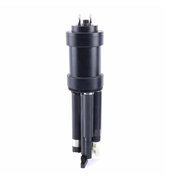
But the LoRaWAN Soil EC Sensor is a precision powerhouse: featuring patented multi-electrode technology, it measures EC, moisture, and temperature simultaneously with ±8% EC accuracy and ±2% moisture error—all in less than 2 seconds! It’s like having a “soil taste tester” that tells you exactly when your crops are “hungry,” “thirsty,” or at risk of salt damage.
Whether you’re managing a greenhouse or restoring saline-alkali land, it eliminates guesswork and gives you data you can trust.
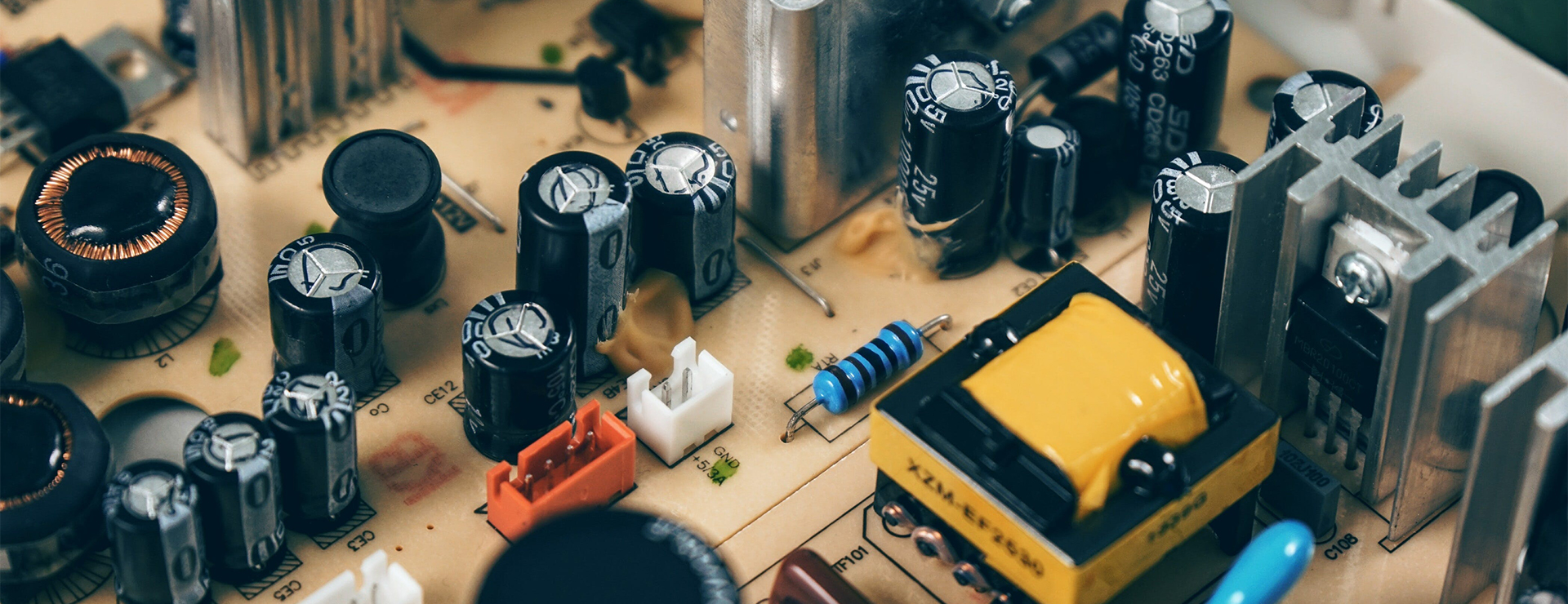
Argument 2: Built to Last – Tough Enough for Any Industrial Job
Industrial environments are brutal—wet swamps, corrosive salt-rich soil, extreme temperatures.
Most sensors fail within months, but the LW Sensor is built for war: IP68 waterproof/dustproof rating, corrosion-resistant stainless steel probes, and a durable design that survives underground burial for years (yes, even submerged in water!).
With RS485 bus support, it can extend up to 1000 meters for distributed monitoring—perfect for 120-acre smart greenhouses or cross-regional ecological projects.
It’s more reliable than your most dedicated team member!
Argument 3: Smart & User-Friendly – Even Beginners Can Master Precision
Industrial-grade doesn’t mean complicated! The LW Sensor is designed for ease: built-in calibration curves deliver ready-to-use data (no math required!), and it seamlessly connects to IoT platforms, data loggers, and mobile apps.
Get real-time alerts when EC levels are too high/low—no more late-night panics over crop health! A greenhouse grower in Shandong, China, saw amazing results: after switching to the LW Sensor, fertilizer use dropped by 40%, water consumption by 50%, and tomato yields increased by 15%—all by keeping EC levels precisely between 1.2-1.5ms/cm.
Whether you’re into precision farming, environmental monitoring, or soil remediation, it cuts 80% of manual work and turns “farming by luck” into “farming by data.”
The Bottom Line:
A sensor isn’t an expense—it’s an investment in less stress and higher profits. The LoRaWAN Soil EC Sensor doesn’t need constant calibration, won’t break down when you need it most, and never gives bad data.
It’s your soil’s personal data analyst, helping you make every drop of water and every gram of fertilizer count. Grab yours today, and while others are still guessing next harvest, you’ll be celebrating record yields.
The LW Soil EC Sensor is your shortcut to smarter, more efficient soil management—no expertise required, just reliable data and bigger yields.Transform how you work with soil. Your next record harvest starts here!
Introduction: The "Invisible Threat" of H₂S Calls for Professional Protection
In many industries such as petrochemicals, sewage treatment, and mining, hydrogen sulfide (H₂S) is an extremely dangerous gas—it is colorless, highly toxic, and can cause discomfort even at low concentrations, while high concentrations can be life-threatening in a short time.
Due to its characteristics of "invisible, detectable by smell but easily ignored", the traditional manual inspection method is not only inefficient but also difficult to achieve real-time and accurate risk early warning. Against this backdrop, the ZONEWU Wireless LoRaWAN Hydrogen Sulfide Sensor came into being, using technological innovation as a fulcrum to build a solid "invisible defense line" for industrial safety.
Core Advantage 1: Empowered by LoRaWAN Technology, Breaking Through Transmission Bottlenecks
As a professional sensor for industrial scenarios, the most prominent advantage of the ZONEWU H₂S Sensor is its integration of LoRaWAN wireless communication technology. Compared with traditional wired transmission, LoRaWAN technology has three core highlights: first, ultra-long transmission distance, which can reach several kilometers in an open environment, and can transmit data stably even in complex scenarios with dense workshops and many wall obstacles; second, ultra-low power consumption design, the sensor adopts a high-efficiency energy-saving chip, combined with an intelligent sleep mechanism, which can work continuously for months or even years after a single charge or battery replacement, greatly reducing the later maintenance cost; third, strong anti-interference ability, which can effectively avoid signal interference from other wireless devices in the industrial environment, ensuring the accuracy and stability of data transmission.
Core Advantage 2: Accurate Monitoring + Fast Response, Building the First Line of Safety
For gas sensors, "accuracy" is the foundation. The ZONEWU H₂S Sensor adopts the high-precision electrochemical detection principle, which can accurately capture hydrogen sulfide gas in the air within the concentration range of 0-100ppm, and the detection error is controlled within ±5%FS, which is far better than the industry average.
At the same time, the sensor has a fast response capability. When the gas concentration reaches the preset threshold, it will not only remind on-site personnel through sound and light alarms locally but also upload the alarm information and real-time concentration data to the cloud platform within 1 second, allowing managers to grasp the risk dynamics in the first time even if they are not on-site, and gain valuable time for emergency response.
Core Advantage 3: Full-Scenario Adaptation, Convenient and Efficient Operation
The diversity of industrial scenarios puts forward high requirements for the adaptability of sensors. The ZONEWU H₂S Sensor adopts an IP67 high protection level design, which is waterproof, dustproof, and corrosion-resistant. It can operate stably whether in a humid sewage treatment tank, a high-temperature chemical reaction area, or a dusty mine tunnel. In terms of installation and operation, the sensor supports multiple installation methods such as wall-mounted, pipeline, and bracket. No complicated wiring project is required, and installation and commissioning can be completed in 10 minutes. The supporting cloud platform also has functions such as data visualization, historical data query, and abnormal data traceability. Managers can realize remote monitoring and management through a computer or mobile APP, which greatly improves the efficiency of safety management.
Practical Application: Safety Protection from Laboratory to Production Line
At present, the ZONEWU Wireless LoRaWAN Hydrogen Sulfide Sensor has been widely used in many fields. In a large petrochemical refinery, sensors are installed in the crude oil extraction and sewage treatment links to monitor equipment leakage in real-time. Since its commissioning, it has successfully warned of 3 minor leaks, avoiding safety accidents; in a municipal sewage treatment plant, the sensor has replaced the traditional manual inspection, which not only increased the inspection efficiency by 80% but also provided a scientific basis for equipment maintenance through data trend analysis; in the mining scenario, the sensor is linked with the emergency system.
Once the H₂S concentration is detected to exceed the standard, it will immediately automatically start the ventilation equipment and cut off the power in the dangerous area, providing strong protection for the life safety of miners.
Conclusion: Guarding Every Bit of Safety with Technological Innovation
In today's era where industrial safety is increasingly valued, the ZONEWU Wireless LoRaWAN Hydrogen Sulfide Sensor has become a powerful assistant for enterprises to prevent H₂S risks with its core characteristics of "accuracy, stability, and efficiency".
It not only solves the pain points in traditional safety monitoring but also promotes the upgrading of industrial safety management models through digital and intelligent means. In the future, ZONEWU will continue to deepen its focus on the gas sensing field, and provide strong support for the safe development of various industries with more advanced technologies and better products.
It was 3 a.m. in the chemical industrial park, and the moonlight stretched the shadows of the pipelines long. Old Zhang's walkie-talkie suddenly crackled with static, followed by the sharp beep of an automatic system alarm— the hydrogen concentration in the eastern storage area had exceeded the warning threshold. He grabbed his safety helmet and rushed to the scene, but halfway there, he received a precise location alert from the sensor node: "Valve interface of Pipeline 3, leak concentration 0.4%, diffusion rate 0.02% per minute." Twenty minutes later, the leak was successfully sealed, and a potential explosion crisis was nipped in the bud. Staring at the stable curve on the equipment screen, Old Zhang recalled the near-disaster caused by a hydrogen leak five years ago and sighed, "Now we don't chase after hidden dangers; the sensors 'shout' them out to us." The wisdom behind making hydrogen—this invisible, intangible "hidden killer"—"speak up" lies in the collaboration between LoRaWAN technology and H₂ gas sensors.
As both a clean energy source and an industrial raw material, hydrogen has long permeated numerous fields such as chemical engineering, energy, and electronics. However, its flammable and explosive properties have always been a "Sword of Damocles" in industrial production—when the hydrogen concentration in the air reaches the explosive limit of 4% to 75.6%, even a tiny spark can trigger catastrophic consequences. Before the popularization of LoRaWAN technology, H₂ gas monitoring had long been trapped in a dilemma: "What is visible is inaccurate, and what is accurate is invisible." Back then, sensors either relied on wired connections, which were costly and inflexible to deploy in large industrial parks, leaving remote pipeline nodes completely uncovered; or they used short-range wireless technology, with a transmission distance of no more than 100 meters, and their data was often scrambled by electromagnetic interference in industrial environments. Old Zhang still remembers that during the leak five years ago, the traditional sensor didn't issue an alarm until 20 minutes after the concentration exceeded the standard. By the time they found the leak point, hydrogen had already spread to the entrance of the operation workshop.
The emergence of LoRaWAN technology is like equipping H₂ gas sensors with "long-distance ears" and "intelligent brains," completely breaking the monitoring predicament. This low-power wide-area network protocol based on spread spectrum technology has three core advantages: "long range, energy efficiency, and stability." Its transmission distance can reach several kilometers or even more than ten kilometers, perfectly matching the vast scale of industrial parks; the battery life of a single sensor node can easily reach 3 to 5 years, eliminating the need for frequent power replacements and solving the power supply problem in remote areas; its anti-interference ability is particularly outstanding—even in industrial environments filled with motors and frequency converters, it can transmit data stably without "distortion." When an H₂ gas sensor is equipped with a LoRaWAN module, it forms a complete closed-loop from "perception" to "transmission" and then to "early warning": the electrochemical element at the core of the sensor captures hydrogen molecules in the air in real time, converts the concentration signal into an electrical signal, encrypts it via the LoRaWAN module, and uploads it to a gateway. The gateway then forwards the signal to a cloud platform, which uses algorithms to analyze and determine whether to trigger an early warning. Finally, alerts are sent to staff through multiple channels such as text messages, APP notifications, and on-site sound and light alarms. The entire process takes less than one second, truly realizing "catching hidden dangers as soon as they appear."
The combination of LoRaWAN and H₂ gas sensors is not just a superposition of technologies, but a revolution in industrial safety concepts—shifting from "passive remedy" to "proactive defense." Behind this transformation, three core arguments support its irreplaceable value. Firstly, its wide coverage solves the "blind spot problem" in industrial monitoring. Traditional monitoring equipment is often concentrated in core production areas, while "edge areas" such as pipeline routes and storage area perimeters tend to become regulatory blind spots. LoRaWAN's long-distance transmission capability allows "full-coverage" deployment of sensors; even in underground pipeline wells, data can be transmitted back to the platform through relay nodes. Secondly, its low-power advantage reduces the "hidden costs" of safety management. For parks with thousands of monitoring nodes, frequent battery replacements not only consume manpower and material resources but also may cause monitoring interruptions during replacement. The long battery life of LoRaWAN sensors fundamentally solves this problem, making safety management more efficient and stable. Thirdly, its data interconnection capability builds an "overall prevention and control network." Early warnings from a single sensor are just "point" reminders, while LoRaWAN technology can aggregate data from all nodes into a "surface" profile. By analyzing the concentration change trends in different areas, the platform can predict the direction of leak diffusion and provide a scientific basis for emergency response—like equipping safety managers with "prescient" eyes.
Today, in chemical industrial parks, more and more H₂ gas sensors are "on duty" with the help of LoRaWAN technology. They attach quietly to pipelines and hide beside equipment, capturing the "breath" of hydrogen 24 hours a day. Old Zhang's role has also changed from a "patrolman" in the past to a "commander" now. He only needs to sit in the monitoring room to grasp the situation of all monitoring points through the screen. Those beating numbers and stable curves form the most reassuring scenery in industrial production.
From invisible hidden dangers to visible data, from passive response to proactive prevention, LoRaWAN technology has transformed H₂ gas sensors from "monitoring tools" to "safety guards." In the wave of energy revolution and industrial intelligence, such technological integration is constantly happening. They may not have a gorgeous appearance, but with every accurate perception and every stable transmission, they strengthen the safety line for industrial production. And guardians like Old Zhang, with the support of these technologies, are making the goal of "zero accidents" increasingly within reach—when hydrogen learns to "speak up," safety gains its most reliable voice.
Turn on the faucet, clear tap water trickles out. This is the most ordinary scene in our daily lives. But have you ever thought that this seemingly simple water has gone through a long, complex, and technologically advanced 'smart journey' from a natural water source to your home faucet? On this journey, it is various water quality sensors that safeguard the safety of every drop of water and play the roles of "sentinels" and "eyes".
Prologue: The 'Frontline Outpost' of the Water Source Area
Our journey starts with rivers, lakes or reservoirs. This is the water source of the city, but it is also the place that initially faced risks.
Real time monitoring and prevention: Multiple parameter water quality monitoring buoy stations or shore stations are deployed at key sections of the water source area. Their built-in sensors are like loyal sentinels, continuously monitoring key indicators such as pH, dissolved oxygen (DO), turbidity, conductivity, ammonia nitrogen, etc. of the water body 24/7.
Early warning, quick response: Once the sensor detects abnormal fluctuations in water quality (such as sudden pH changes or abnormal decrease in dissolved oxygen, which may indicate a pollution event), the system will immediately issue an alarm. The water department can quickly initiate emergency investigations, trace the source of pollution, and nip water pollution in the bud before it affects the water supply system. This has won valuable pre-treatment time for downstream water plants.
Core battlefield: the "smart brain" of the water plant
The raw water passes through the water intake pump room and enters the water treatment plant. This is the core link in turning "raw water" into "purified water", and it is also the "main battlefield" where water quality sensors can showcase their capabilities.
Coagulation and sedimentation stage: In this stage, turbidity sensors are the absolute protagonists. It accurately monitors the content of suspended particles in water, feeds back data to the dosing system, and intelligently adjusts the dosage of coagulants (such as polyaluminum chloride). It not only ensures the sedimentation effect, but also avoids the waste of reagents, achieving precise dosing.
Filtering process: The water that has been precipitated will be filtered through filter media layers such as quartz sand and activated carbon. The turbidity sensor and particle counter at the outlet ensure that the filtered water meets strict clarity standards.
Disinfection process - the core level of safety: This is the last and most important step in ensuring the microbiological safety of drinking water. The residual chlorine sensor is crucial here. It continuously monitors the residual chlorine content in water to ensure that it remains within a precise range that can effectively kill pathogenic microorganisms without producing excessive disinfection by-products such as trihalomethanes. In addition, ozone concentration sensors and ultraviolet intensity sensors also play a similar key control role in other disinfection processes.
Clear water storage and factory water: The treated clear water must undergo a final "physical examination" before being sent to the municipal pipeline network. A complete sensor system will comprehensively check dozens of indicators such as pH, turbidity, residual chlorine, conductivity, etc. of the factory water to ensure that every drop of water meets 100% of the national "Sanitary Standards for Drinking Water"
It can be said that modern water treatment plants have transformed from traditional workshops relying on human experience to automated intelligent factories driven by data. And the source of all this data is the sensors scattered throughout the process.
The last kilometer: the "nerve endings" of the municipal pipeline network
The journey of water does not end after leaving the factory. Transported to thousands of households through a massive municipal pipeline network, this' last mile 'also carries water quality risks (such as secondary pollution).
Smart water management continuously monitors core indicators such as residual chlorine and turbidity by installing miniaturized and integrated water quality monitoring terminals at key nodes of the pipeline network, such as community entrances and high-level water tanks. These data are transmitted back to the control center in real-time. Once the residual chlorine content in a certain area is found to be too low (which may lead to bacterial growth) or the turbidity is abnormally high (which may indicate pipeline damage), the system can quickly locate the problem area, dispatch maintenance teams in a timely manner, and ensure the safety of the faucet water.
Conclusion: The Invisible Guardian
From the source of the river to the faucet at home, water quality sensors have built an ubiquitous perception network. They are the 'sensory nerves' of smart water management and the unsung heroes who ensure safe, efficient, and reliable water supply.
Through real-time and accurate data collection, they not only achieve refined management and energy conservation in the water treatment process, but more importantly, build a solid water safety defense line for us. The next time you easily drink a glass of water, remember that there is also a credit from these silent yet wise 'guardians'.
In the future, as sensor technology develops towards miniaturization, intelligence, and lower cost, the perception network of smart water will become increasingly dense and powerful, bringing us a safer, more efficient, and sustainable era of water use.
Choosing a LoRaWAN water quality calcium ion sensor suitable for specific application scenarios requires comprehensive consideration of measurement requirements, environmental conditions, sensor performance, communication capabilities, cost, and other factors. The following are specific selection points:
1. Clarify measurement requirements
Measurement range: Determine the required calcium ion concentration range according to specific application scenarios. For example, in general surface water monitoring, calcium ion concentration may be in the tens to hundreds of milligrams per liter, while in some industrial wastewater or special water treatment scenarios, the concentration range may be wider.
Accuracy requirements: Different applications have varying precision demands. For instance, drinking water treatment requires high precision for calcium ion concentration, typically needing to achieve a ±1% - ±2% F.S. (Full Scale). In contrast, agricultural irrigation scenarios with relatively lower precision requirements may find that an accuracy of ±5% F.S. is sufficient to meet the needs.
Resolution: refers to the minimum concentration change that the sensor can detect. If it is necessary to monitor subtle concentration changes, such as in the study of calcium ion dynamic changes in water, it is necessary to choose a high resolution sensor, such as the ability to identify 0.1 mg/L of concentration change.
2. Consider environmental conditions
Temperature and humidity: Different sensors work differently in different temperature and humidity ranges. For example, in a high temperature and humidity environment, it is necessary to choose a sensor with good temperature compensation and moisture protection to ensure measurement accuracy and stability.
Corrosion: If the water is corrosive, such as containing a high concentration of acid and alkali substances or other corrosive ions, the sensor with corrosion-resistant shell and sensitive elements should be selected, such as the sensor made of stainless steel or special anticorrosive materials.
Electromagnetic interference: in some industrial environments or places with strong electromagnetic interference, it is necessary to choose the LoRaWAN calcium ion sensor with anti-electromagnetic interference ability to avoid signal transmission interference and ensure the accuracy and reliability of data.
3. Evaluate sensor performance
Stability: Stability refers to a sensor's ability to maintain consistent performance over extended use. Selecting sensors with excellent stability can reduce calibration frequency and maintenance costs, ensuring long-term measurement accuracy. Key indicators to consider include zero drift and span drift measurements, along with stability test reports provided by manufacturers.
Sensitivity: Sensors with high sensitivity can detect small changes in calcium ion concentration more accurately, but they are also more susceptible to external noise. Therefore, it is necessary to choose sensors with high signal-to-noise ratio to ensure reliable measurement results while maintaining high sensitivity.
Response time: For real-time monitoring and rapid response application scenarios, such as real-time discharge monitoring of industrial wastewater, sensors with short response time should be selected to detect changes in calcium ion concentration and take corresponding measures in time.
4. Focus on communication skills
Communication Protocol: Ensure the sensor supports the LoRaWAN communication protocol and is compatible with existing LoRaWAN network infrastructure, including gateways and servers. Additionally, verify that the sensor's frequency band complies with local regulations and application requirements, such as CN470, EU868, or US915 frequency bands.
Transmission distance: Select sensors with appropriate transmission distance based on the scope of the application scenario. For example, in monitoring large areas of lakes or reservoirs, sensors need to be able to stably transmit data over long distances, while in some relatively small enclosed water bodies, shorter transmission distances may be sufficient.
Power consumption: As LoRaWAN sensors typically operate on battery power, energy efficiency is a critical consideration. Low-power sensors can extend battery life, reduce maintenance costs, and minimize the frequency of battery replacements. Key parameters to monitor include sleep current, operating current, and battery runtime duration.
5. Consider installation and maintenance
Sensor dimensions and installation methods: Select sensors with appropriate sizes and mounting options based on actual installation locations and spatial constraints. For instance, compact sensors with easy-to-install features are recommended for narrow pipelines or equipment, while outdoor water monitoring applications typically require sensors with secure mounting solutions and protective designs.
Calibration and Maintenance: Understand the calibration methods and frequency requirements for sensors, and select those that are easy to calibrate and maintain. Some sensors may require regular calibration using standard calcium solutions, while others may have automatic calibration features that reduce the workload of manual maintenance.
6. Comprehensive cost factors
Procurement cost: different brands, models and performance of the sensor price varies greatly, under the premise of meeting the application requirements, choose the cost-effective sensor. But do not only take price as the only selection criteria, but ignore the performance and quality of the sensor.
Operating costs: include battery replacement costs, communication costs (if any), and maintenance costs. Low-power, long-life sensors can reduce operating costs, while some sensors that require frequent calibration and maintenance may increase the cost of later use.
The selection of soil EC sensors suitable for agricultural applications requires a comprehensive consideration of several factors. The following are some key points:
Measurement range: Generally speaking, the measurement range of 0-20000μS/cm can cover most soil types, from mild salinization to severe saline-alkali land, which can meet the needs of most agricultural scenarios.
Measurement Accuracy:For most agricultural applications, sensors with an accuracy of ±3% within the range of 0-10,000 μS/cm and ±5% accuracy within the range of 10,000-20,000 μS/cm can meet the requirements. However, in scenarios with higher precision demands such as scientific research, more accurate sensors like the OSA-6 soil conductivity sensor should be selected, which achieves measurement accuracy of ±2%.
Resolution:High resolution can clearly distinguish the small changes of soil EC value. Generally, the resolution is 10μS/cm in the range of 0-10000μS/cm, and 50μS/cm for the sensor in the range of 10000-20000μS/cm is more ideal.
Temperature compensation function: soil EC value is greatly affected by temperature, so it is very important to choose a sensor with automatic temperature compensation function, which can ensure accurate measurement of soil EC value in different temperature environments. For example, SEN0603 RS485 soil sensor has memory temperature compensation function, and the compensation range is 0-50°C.
Common output signal types include voltage signals (e.g., 0-2V,0-5V,0-10V), 4-20mA current loops, and RS485. For applications requiring long-distance data transmission or IoT integration, RS485 sensors that support standard Modbus-RTU protocols are particularly suitable. These sensors offer strong anti-interference capabilities and facilitate system integration.
Protection class:In agricultural environment, the sensor may need to be directly buried in the soil, so the protection class should be high. Generally, the sensor with protection class up to IP68 should be selected, which can ensure that the sensor has good waterproof and corrosion resistance performance, and can work stably for a long time in the harsh soil environment.
Probe Material: The probe material should possess excellent corrosion resistance and conductivity. Common materials include 316 stainless steel and graphite. For example, the probe of the SEN0603 RS485 soil sensor is made of 316 stainless steel, which features rust prevention, waterproofing, corrosion resistance, and salt-alkali resistance, allowing long-term burial in soil.
Data storage capacity:If it is necessary to monitor the soil EC value for a long time and it is not convenient to transmit the data in real time, it is more appropriate to choose the sensor with large data storage capacity. For example, if the sensor can store more than 300,000 pieces of data, it can meet the data recording needs of large-scale plots and long-term projects.
Power supply mode: Select the appropriate power supply mode according to the use scenario. If it is in a greenhouse with stable power supply, sensors with DC power supply (such as 12V,24V) can be selected; if it is in an outdoor environment without power supply, low-power sensors with battery power or solar power can be considered.
Water is the source of life and the foundation of ecology. From rivers, lakes, and seas to the faucets of thousands of households, the safety of water quality is directly related to ecological security, people's health, and sustainable economic and social development. In the past, monitoring water quality was a tedious and time-consuming task that required manual sampling and laboratory analysis. It was not only inefficient, but also had pain points such as data lag and weak representativeness. Nowadays, with the rapid development of technology, a "smart eye" that integrates multiple functions - a water quality multi parameter sensor - is completely changing the way we perceive and understand the water world.
1、 What is a water quality multi parameter sensor?
The water quality multi parameter sensor is a highly integrated intelligent monitoring device that can simultaneously, continuously, and in situ measure multiple key physical, chemical, and biological indicators in water using advanced sensing technology.
Its core charm lies in the integration of "multiple parameters". In traditional methods, measuring pH value, dissolved oxygen (DO), conductivity (TDS), turbidity, etc. requires different instruments and reagents. Multi parameter sensors ingeniously integrate multiple independent sensor modules into a probe or a compact system, allowing for a complete set of water quality data to be obtained with just one deployment, greatly improving monitoring efficiency and convenience.
Common core monitoring parameters include:
Physical indicators: temperature, turbidity, conductivity (total dissolved solids TDS can be calculated).
Chemical indicators: pH value, oxidation-reduction potential (ORP), dissolved oxygen (DO).
Comprehensive indicators: chemical oxygen demand (COD), ammonia nitrogen (NH3-N), nitrate (NO3-), chlorophyll-a, blue-green algae, etc. (specific sensor modules are required).
2、 Core technology principles and advantages
The technological cornerstone of multi parameter sensors is various advanced sensing technologies, such as photoelectric sensing, electrochemical sensing, ultrasonic sensing, etc.
PH sensor: Typically, the glass electrode method is used to measure the hydrogen ion concentration by measuring the potential difference on both sides of the glass film.
Dissolved oxygen sensor: The mainstream method is fluorescence quenching (optical method). The fluorescent substance on the surface of the sensor is excited by light of a specific wavelength, and the concentration of oxygen in the water affects the fluorescence intensity and lifetime. By measuring these changes in optical properties, the dissolved oxygen content can be accurately calculated. This method does not require electrolyte, requires minimal maintenance, and has high stability.
Turbidity sensor: It often uses the principle of 90 ° or 180 ° scattered light to emit a beam of light and measure the intensity of light scattered by suspended particles in water, thereby determining the degree of turbidity of the water.
Conductivity sensor: Based on Ohm's law, its conductivity is calculated by measuring the resistance of water between two electrodes.
Its significant advantages lie in:
Real time and continuity: Provides a 7x24 hour uninterrupted data stream that can capture transient and sudden abnormal changes in water quality, which cannot be compared to manual sampling.
In situ monitoring: Sensors are directly placed in the tested water body, avoiding potential qualitative changes that may occur during sample transportation and storage, resulting in more authentic and representative data.
High efficiency and low cost: One machine can be used for multiple purposes, saving the cost and time of frequent sampling and extensive laboratory analysis. In the long run, the comprehensive benefits are extremely high.
Integration and Intelligence: Deeply integrated with modern Internet of Things (IoT) technology, data can be transmitted in real-time to cloud platforms through wireless technologies such as 4G/5G, LoRa, NB IoT, etc., enabling remote monitoring, big data analysis, and intelligent warning.
3、 Widely applicable scenarios
This' Eye of Wisdom 'is playing a crucial role in various industries:
Environmental monitoring and ecological protection: used for long-term ecological monitoring of rivers, lakes, reservoirs, oceans and other water bodies, assessing environmental risks such as eutrophication and algal blooms, and providing data support for governance decisions.
Smart City and Water Management: Installed at the inlet, process treatment unit, and outlet of water plants to achieve closed-loop monitoring of water quality throughout the entire process, ensuring the safety of drinking water; Used for monitoring the inflow and outflow of urban drainage networks and sewage treatment plants to improve operational efficiency.
Aquaculture: In high-density aquaculture ponds, key parameters related to fish survival such as pH and dissolved oxygen are monitored in real-time. Once abnormal, an alarm is immediately triggered and equipment such as aerators can be linked to effectively avoid risks and reduce economic losses.
Industrial process and emission monitoring: In industries such as food, pharmaceuticals, and chemicals, monitor the quality of water used in production processes; At the same time, strict monitoring of wastewater discharge from enterprise sewage outlets to ensure compliance with standards is the "frontline sentry" of environmental protection supervision.
Scientific research and hydraulic engineering: providing high-frequency and high-precision raw data for scientific research in fields such as hydrology, geology, and environment; Used for ensuring water quality and safety in large-scale water transfer projects such as the South to North Water Diversion Project.
4、 Challenges and Future Prospects
Despite its outstanding advantages, multi parameter sensors also face some challenges: biofouling can affect sensor accuracy, requiring advanced anti pollution materials or automatic cleaning devices; The complex water environment places higher demands on the long-term stability and anti-interference ability of sensors; Meanwhile, the high initial investment and professional maintenance requirements have also to some extent limited its popularity.
Looking ahead to the future, the development of multi parameter water quality sensors will present the following trends:
Miniaturization and lower power consumption: Sensors based on MEMS (Micro Electro Mechanical Systems) technology will be smaller and more energy-efficient, suitable for mobile monitoring platforms such as drones and underwater robots, as well as long-term unmanned scenarios.
Higher integration and more parameters: In the future, a sensor may be able to integrate dozens of monitoring functions, even including difficult to measure indicators such as heavy metals and organic pollutants.
Self cleaning and self calibration: The application of intelligent materials and new technologies will effectively solve the problem of biological pollution and achieve self diagnosis and automatic calibration of sensors, greatly reducing maintenance costs.
Deep integration of artificial intelligence: Combining AI algorithms, sensors can not only provide data, but also perform trend prediction, pollution tracing, and intelligent diagnosis, moving from "perception" to "cognition" and "decision-making".
Conclusion
The water quality multi parameter sensor, the "smart eye" that insight into the water world, has become an indispensable core infrastructure for building digital water management and smart environmental protection. It makes the previously invisible changes in water quality clear, visible, manageable, and controllable. With the continuous evolution of technology and the continuous decline of costs, it will inevitably integrate deeper and wider into our lives, providing unprecedented powerful momentum for safeguarding that clear water and ensuring global water security.
Is Real-Time Water Quality Monitoring Worth It for Modern Water Management
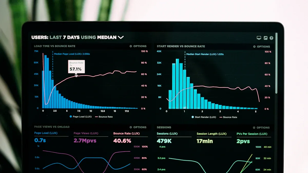
I think real-time water quality monitoring is a helpful tool for modern water management. Many utilities around the world use real-time systems. Over 63% have started using them, as shown below:
Region
Adoption Percentage of Real-Time Water Quality Monitoring Systems
Global Utilities
Over 63%
Europe
About 61%
Asia-Pacific
Over 54%
Middle East & Africa
Around 41% (new projects)
Urban Utilities
Over 62%
Industrial Facilities
39%
From what I have seen, real-time sensors for water quality give these main benefits:
I get fast data and early warnings about water problems.
I can make better choices because I see data all the time.
I save money compared to using lab tests.
But there are also some problems:
The costs are high, and the technology is hard to use and keep working.
I have to protect the data and make sure the sensors work well.
Real-time water quality monitoring gives quick data and early warnings. It helps people find problems fast and keep water safe. Continuous monitoring helps people make better choices. It shows how water changes over time. It also helps find pollution sources early. Modern sensors check many water quality factors at the same time. This gives a complete view and saves time and money. Setting up real-time systems can cost a lot and be hard to do. You need skilled workers and regular care to keep sensors working right. Picking the best monitoring method depends on your goals, budget, and water conditions. This helps manage water well and keeps people healthy.
Benefits of Continuous Water Quality Monitoring Systems
Continuous water quality monitoring systems help me manage water better. These systems give me real-time data, so I always know what is happening. I do not have to wait a long time for lab results. Before, I sent samples to a lab, and it took about 4.6 days. Now, with real-time sensors and artificial intelligence, I get alerts in about 2.7 days or even faster. I can find problems like contamination right away. This helps me act fast to keep people and the environment safe.
These systems use sensors that collect data all the time. The sensors send real-time data to my computer or phone. If something changes quickly, I get an alert. I do not worry about missing a problem because the system watches the water for me. There are fewer mistakes because the sensors work by themselves. I do not have to worry about human error or sample contamination. This makes my monitoring more accurate and reliable.
Tip: Real-time data collection helps me stop water quality threats before they get worse.
Improved Decision-Making
When I get real-time data from continuous water quality monitoring systems, I make better choices. I can watch how water quality changes over time. I see patterns and find where pollution comes from. This helps me know when to act and what to do. I work with others, like government agencies and researchers, who also use this data. Together, we protect public health and the environment.
Here are some ways real-time data helps me make better decisions:
I do not wait for lab results, so I act before things change.
I find threats to water systems and public health early.
I share instant data with others, even if they are far away.
I follow rules from local, state, and federal agencies.
I build stronger water systems that can handle emergencies.
I have seen real examples where continuous water quality monitoring systems made a big difference. At Edgewater Beach, real-time monitoring helped find bacteria problems fast. In the Clinton River watershed, I used real-time data to respond to storms and protect water quality. These systems also help me try new technologies and grow my monitoring network.
Note: Checking water quality monitoring data often helps me make smart, evidence-based choices for water management.
Comprehensive Parameter Detection
Continuous water quality monitoring systems let me measure many things at once. I use sensors that check physical, chemical, and biological parameters. This gives me a full picture of water quality. I can see changes in pH, temperature, turbidity, and conductivity. I also track chlorine, nitrogen, and bacteria like E. coli.
Here is a table showing what I can detect with modern continuous water quality monitoring systems:
I use iot-based monitoring to connect these sensors to the internet. This way, I get real-time data from many places at once. I can map water quality changes and find problems faster. Iot-based monitoring also helps me keep my data safe. I use encryption and access controls to protect important information. I can even let the public help with water quality monitoring through citizen science projects.
Iot-based monitoring gives me 24/7 access to water quality data.
I use advanced platforms for data visualization and early warnings.
I save money by using fewer people and more automation.
I keep my data safe with strong cybersecurity measures.
With continuous water quality monitoring systems, I help manage water in a smart way. I make sure water stays safe, clean, and good for everyone.
Challenges of Water Quality Monitoring
High Costs and Maintenance
When I started learning about water quality monitoring, I saw it was expensive. Setting up a real-time system means buying special equipment and building things to hold it. I also need to train people to use the system. For small towns or businesses, these costs can be too high. Even a simple IoT-based water quality monitoring system can cost more than $2,400 just for the hardware. If I want more features or more places checked, the price goes up.
Old water quality monitoring systems need a lot of money at the start. I have to pay for tools, putting them in, and sometimes new buildings for the equipment. After that, I still pay for regular care, fixing, and skilled workers to keep it working. Manual sampling costs more because it takes time and people.
Now, some companies let me rent everything with a monthly fee. This is called Infrastructure as a Service (IaaS). The fee covers hardware, software, care, training, and supplies. I do not need to buy new equipment or pay for repairs. The monthly fee also pays for internet, so I do not get extra bills. If I want to check new things in the water, I can add them without buying new sensors.
Here is a table that compares the old way and the IaaS way:
Cost Factor
Traditional Model
IaaS Model
Upfront Equipment
High
None
Maintenance
Separate, ongoing
Included in monthly fee
Calibration
Manual, frequent
Automated, less frequent
Consumables
Extra cost
Included
Connectivity
Extra cost
Included
Flexibility
Low
High
Smart sensors, like dissolved oxygen sensors, need less care than old test kits. These sensors can work for months without cleaning or fixing. They use less power and can even clean themselves. This saves time and money, but I still need someone who knows how to set up and check the system.
Note: Even with new ways and smart sensors, water quality monitoring still needs regular care and skilled workers to keep it working well.
Technical Complexity
Water quality monitoring is now more advanced, but also harder to use. I need sensors that can measure many things, like pH, dissolved oxygen, and bacteria. These sensors must work all the time, even in tough places. Sometimes, algae and dirt build up on the sensors. This is called biofouling. It can make the readings wrong and the data less useful.
Some sensors use special lights or brushes to clean themselves. For example, the UviLux sensor uses UV light to stop biofouling. Other sensors can go up to two years without needing calibration. This helps, but I still need to check them and make sure they work right.
Here are some technical problems I face with water quality monitoring:
Sensors must work well in all weather.
I need to collect data all day and night.
It is hard to find where pollution comes from, especially in rivers or near the sea.
I need to make sure the data is right and the sensors are set up well.
Sometimes, I need to fix broken parts or change cables.
I also need people with special skills to set up, fix, and check the sensors. These experts help me follow the rules and keep the system working. In some places, it is hard to find people with the right skills, which makes it harder to use advanced water quality monitoring systems.
Tip: Training and help are important to make sure my water quality monitoring system works well and gives me good data.
Data Management Issues
When I use continuous water quality monitoring, I get lots of data. Managing this data can be hard. Sometimes, algae or other tiny things grow on the sensors and cause bad readings. I use sondes with wiper brushes to clean the sensors and keep the data right.
Other problems are broken parts, old equipment, and cable problems. These issues can stop the sensors from sending data. I also have to deal with new rules and laws, so I need technology that can change when needed.
Here are some common data management problems I face:
Biofouling on sensors causes bad data.
Broken equipment means missing data.
New laws make me change how I collect and store data.
Bad calibration or wrong settings waste time and money.
Training is needed so everyone knows how to use the equipment and understand the data.
To handle all this data, I use cloud-based platforms. These tools help me store, study, and see the data from my water quality monitoring system. I can spot trends, get alerts, and make choices faster. Some platforms use smart technology to find problems before they get worse. They let me check my data from anywhere, using my phone or computer.
Callout: Smart data platforms help me handle lots of data, cut down on problems, and keep my water quality monitoring system working well.
When I pick a water quality sensor, I check what it measures and how well it works outside. There are many sensor types, and each does something different. Some sensors use light to find particles in water. Others use electricity or even living things to spot problems. I often use more than one sensor to get a full idea of water health.
Here is a table that lists the main sensor types and what they measure:
Sensor Type
Parameters Measured
Application/Notes
Temperature Sensors
Water temperature
Non-contact infrared measurement for process control
pH Sensors
Acidity/alkalinity (pH)
Maintains balanced water chemistry
Dissolved Oxygen Sensors
Oxygen levels
Monitors aquatic ecosystem health
Conductivity Sensors
Water conductivity (salinity)
Detects changes in salinity
Turbidity Sensors
Water cloudiness (suspended particles)
Assesses water clarity and quality
ORP Sensors
Oxidation-Reduction Potential
Evaluates water's ability to break down contaminants
I use water quality sensor technology to watch pH, dissolved oxygen, temperature, and turbidity. Some sensors, like ultrasonic and digital thermometer sensors, help me check distance and temperature. Biosensors use living things to find certain pollutants. Each water quality sensor has good points and weak points. Dissolved oxygen sensors are very good at finding low oxygen, so I can spot pollution. Turbidity sensors show if there are lots of particles, but sometimes harmless things can change the reading.
Tip: I always pick the water quality sensor that fits the problem I want to fix.
Calibration and Reliability
To trust my water quality sensor data, I need to keep the sensors calibrated. I usually calibrate pH, dissolved oxygen, and turbidity sensors every month. If the water is dirty or the sensors are old, I calibrate more often. Optical sensors, like dissolved oxygen sensors, stay accurate longer and do not need as much calibration. Electrochemical sensors, like pH sensors, can drift and need more checks.
Things in the environment can make my sensors less reliable. Very hot or cold weather, algae, and chemical spills can hurt a water quality sensor or make it give wrong numbers. I put my sensors in places with shade and not too much water flow. I store them in cool, dry spots when I am not using them. Cleaning and fixing sensors quickly helps them last longer.
I look for sensor drift and fix problems fast.
I use certified standards when I calibrate.
I keep records to make sure my water quality sensor data is right.
Note: Good sensors and regular calibration help me trust my water quality monitoring results.
Real-World Applications
Municipal and Industrial Use
Continuous water quality monitoring systems have changed how cities and factories handle water. In city water utilities, I use real-time monitoring to keep drinking water safe. Some systems use live Bluegills as biological indicators. These fish help me find over two thousand toxic chemicals fast. The BG-n system uses the breathing of Bluegills to spot very small amounts of contaminants. This method gives me early warnings and helps me follow rules. It keeps people safe.
I also use remote monitoring for wastewater. When I put real-time sensors at sewer lift stations, sewer overflow events dropped by 80%. I saved 1,200 labor hours because I did not need as many site visits. Real-time alerts let me fix problems before they become spills or backups. This makes wastewater management more reliable and helps me avoid fines.
In factories, I use water quality monitoring to meet strict rules from agencies like the EPA. I track pH, turbidity, and dissolved oxygen in real time. This helps me keep wastewater safe and avoid shutdowns. Automated controls use live data to change treatment steps. This saves chemicals and helps equipment last longer. By using continuous water quality monitoring, I follow rules and work more efficiently.
Rural and Resource-Limited Settings
In rural areas, I face many problems with water quality monitoring. There is often not enough money or skilled workers. Power and internet can be a problem. Sometimes, I cannot get the right equipment or keep it working. People may worry about privacy or who owns the data. These problems make it hard to set up real-time monitoring for wastewater.
Here are some common challenges I see in rural and resource-limited places:
Not enough money or policy support
Not enough skilled workers
Problems with power and internet
Trouble getting equipment
High starting costs and infrastructure needs
Gaps in data and trouble connecting systems
Even with these problems, I have seen success with low-cost solutions. In the Lake Victoria Basin, I helped set up a wireless sensor network with cheap sensors and cellular data. This system gave real-time alerts and helped people respond to pollution faster. In another project, I used electrochemical sensors with solar power and GSM technology. The results were as good as lab equipment, but the system cost much less.
Here is a table showing some successful low-cost monitoring projects:
Location/Region
Technology/Approach
Key Outcomes/Findings
Falling Water River Watershed, USA
Low-cost real-time water level monitoring
Cost-effective for flood monitoring in resource-constrained communities.
Andean region, Venezuela
Wireless sensor network for flood alerting
Useful for regions lacking infrastructure and resources.
Dublin, Ireland
Low-cost sensor network
High accuracy compared to commercial sensors; good for watershed monitoring.
Urban stormwater systems, USA
Ultrasonic depth sensors with internet control
Real-time monitoring and remote control improved stormwater management.
By using the right technology and thinking about what the community needs, I help rural areas improve water quality monitoring and wastewater management, even when resources are limited.
Making the Decision
When to Invest
Before I pick a water quality monitoring system, I think about my goals. I make sure my plan matches what I need to do and the rules I must follow. I focus on places that pollute the most. This helps me spend money wisely and fix problems faster. Sometimes, I need to check water more after big storms because pollution can go up. I set up some sites to check often and others to watch for a long time.
Here are things I think about before spending money on real-time water quality monitoring:
I see if my plan matches my goals and actions.
I find the biggest pollution sources to focus on.
I test more when pollution is likely, like after storms.
I balance my network with quick-check and long-term sites.
I make sure I can spot changes in water quality in time.
I check my budget to see if I can test more often.
I use new tools, like remote sensors, to save money.
I pick fewer but more important sites to lower costs.
I think about cost, how often I test, and how well I can show results.
I have learned that real-time systems help more in some places than others. For example, at Lake Kinneret, many users and fast changes mean real-time systems are worth it. But at Lough Gara, high upkeep costs make it less useful. I always look at how many people use the water, how often it changes, and my budget before I decide.
Tip: I choose real-time water quality monitoring when I need quick action, have lots of users, or face pollution often. This helps me manage water better and keep people safe.
Alternatives to Real-Time Monitoring
Sometimes, I use other ways to check water quality. Lab tests are very accurate, but they cost a lot and need trained workers. I use labs when I need the best results or must test things sensors cannot find. Hybrid ways, like using a phone and test strips, let me check water outside. These ways are cheaper and easy, but not perfect for every test.
Here is a table that compares different water quality monitoring methods:
Method
Accuracy
Cost
Best Use Case
Limitations
Lab-based Testing
Very High
High
Detailed analysis, rare events
Expensive, slow
Hybrid Human–Machine (Colorimetric)
Good
Low
Field checks, resource-limited areas
Less precise for some tests
Remote-Controlled Boat System
Good
Low
Mobile sampling, hard-to-reach places
Needs operator, limited samples
I also use spot checks for short-term problems, like spills or sudden changes. This works well if I have little money, few workers, or only need to check water sometimes. For slow-changing water, like deep wells, checking once in a while is enough. If I need to see trends or act fast, I pick real-time monitoring.
Note: I pick the way that fits my needs, budget, and water type. This helps me manage water smartly and handle wastewater well.
Real-time water quality monitoring helps me get quick data and early warnings. It lets me make better choices about water. But it can cost a lot and be hard to use. There are also problems with handling all the data. I think if it is worth it depends on how big my system is and what I have. I use special tools to help me decide what to do. Robust Decision Making helps me deal with things I am not sure about and find good answers. The XLRM Framework helps me break big problems into smaller parts so I can check them better.
Framework/Tool
How It Helps Me Decide
Robust Decision Making
Handles uncertainty and finds strong solutions
XLRM Framework
Breaks down problems for clear evaluation
I always make sure I know what I want to do. I pick the best places to check water. I choose the technology that fits what I need. Doing these things helps me keep water safe and reach my group’s goals.
In traditional impressions, aquaculture is often associated with "relying on the weather" and "empiricism". Masters judge the quality of water by observing the color of the water, weather, and the behavior of the livestock. This is not only labor-intensive, but also like a gamble - a sudden deterioration of water quality can lead to the complete annihilation of the army and cause huge economic losses.
However, a silent revolution driven by the Internet of Things (IoT) and intelligent sensing technology is happening in ponds, cages, and recirculating aquaculture systems (RAS) around the world. Water quality sensors are the core of this revolution, fundamentally changing the mode of aquaculture and elevating it to an efficient, accurate, and safe modern industry.
1、 Why is water quality so critical?
Before delving into sensors, we first need to understand that water is to aquatic organisms what air is to us. The water quality parameters directly determine the survival, health, and production efficiency of aquaculture products. Several core indicators include:
Dissolved oxygen (DO): the foundation of life. Hypoxia can lead to slow growth, stress, and even widespread death.
PH value (acidity or alkalinity): It affects the metabolism and immunity of aquaculture products, and extreme pH values are toxic.
Temperature: directly affects metabolic rate, food intake, and growth rate.
Ammonia nitrogen (NH ∝ - N): Produced by the decomposition of livestock excrement, it is highly toxic and is the main stressor that induces diseases.
Nitrite (NO ₂ - N): an intermediate product of ammonia nitrogen conversion, also highly toxic.
The traditional manual detection method usually only measures 1-2 times a day and cannot capture the dynamic changes in water quality, especially during the dangerous period with the lowest dissolved oxygen at night, making it difficult for management personnel to continuously monitor.
2、 Water quality sensor: the "digital sensory" of breeders
Water quality sensors are like "underwater sentinels" that work tirelessly 24/7, continuously converting chemical and physical signals in the water into precise digital data. These sensors are deployed in the water body and transmit data in real-time to the central control platform or the breeders' mobile app through wired or wireless means.
Common types of sensors include:
Optical dissolved oxygen sensor: Based on the principle of fluorescence quenching, it is more stable and requires less maintenance than traditional electrode methods.
PH/ORP sensor: uses glass electrodes to continuously monitor the acidity and redox potential of water bodies.
Ammonia nitrogen/ion selective electrode (ISE) sensor: directly monitors the concentration of toxic non ionized ammonia.
Multi parameter water quality monitoring instrument: one probe integrated with temperature pH、DO、 Various functions such as conductivity.
3、 How to improve the efficiency and safety of aquaculture?
1. From "experience farming" to "precision farming", greatly improving efficiency
Accurate feeding: Based on real-time dissolved oxygen and water temperature data, the optimal feeding time for aquaculture can be determined. For example, increasing the feeding amount when dissolved oxygen is sufficient, and reducing or even stopping feeding when dissolved oxygen is low, to avoid feed waste and water pollution. According to statistics, this can save 10% -20% of feed costs.
Optimizing growth environment: The system can automatically record the water temperature change curve, allowing breeders to choose the season that is most suitable for the growth of breeding varieties, or create the best environment by adjusting water depth and other measures, significantly shortening the breeding cycle.
Reduce labor costs: There is no need for technicians to frequently conduct manual measurements at each pond mouth. One person can monitor large breeding areas through mobile phones or computers, greatly reducing labor intensity and labor costs.
2. Build an intelligent system of "warning regulation" to comprehensively ensure safety
7x24 hour risk warning: The system can set safety thresholds for key indicators such as dissolved oxygen and ammonia nitrogen. Once the data is abnormal, it will be immediately alerted through SMS, APP push, sound and light, etc., so that breeders can take intervention measures hours or even tens of hours before the accident occurs, turning passive remedies into active warnings.
Intelligent linkage control: The most advanced system can already achieve automatic control. When the dissolved oxygen is lower than the set value, the system will automatically turn on the aerator; When the pH value deviates from the range, the dosing system can be automatically activated. This kind of immediate response is something that humans cannot achieve and can effectively avoid major accidents such as nighttime hypoxia.
Traceability and decision support: All historical data is fully recorded, forming a 'breeding log'. If there is a problem, it can be traced back to analyze the trajectory of water quality changes and quickly locate the cause. Meanwhile, big data analysis can help optimize breeding strategies and provide scientific basis for future production plans.
Ensuring product safety and sustainability: Good water quality means reducing the occurrence of diseases, thereby reducing the use of antibiotics and chemical drugs, and ensuring the quality and safety of aquatic products from the source. At the same time, precise feeding and medication also reduce pollution to the surrounding environment, making aquaculture more environmentally friendly and sustainable.
4、 Future Trends and Challenges
In the future, water quality sensing technology will develop towards greater precision, durability, and lower cost. The combination with artificial intelligence (AI) will be the next trend - AI models can not only provide early warning, but also predict the trend of water quality changes in the future by analyzing historical data and real-time information, truly achieving intelligent management.
Of course, challenges still exist, such as the problem of long-term biological pollution (scaling) of sensors underwater, and the threshold for initial investment costs for small and medium-sized farmers. But with the popularization of technology and the decrease in cost, water quality sensors will inevitably become a standard configuration for every modern breeder, just like smartphones.
Conclusion
The water quality sensor may seem like a simple data collection device, but it is a key bridge connecting traditional aquaculture and smart agriculture. It endows breeders with the ability to perceive the underwater world, transforming the breeding process from a vague "art" to a clear "science". Embracing this new trend is not only a business decision to enhance profitability, but also a necessary path towards responsible, sustainable, and safe modern aquaculture.
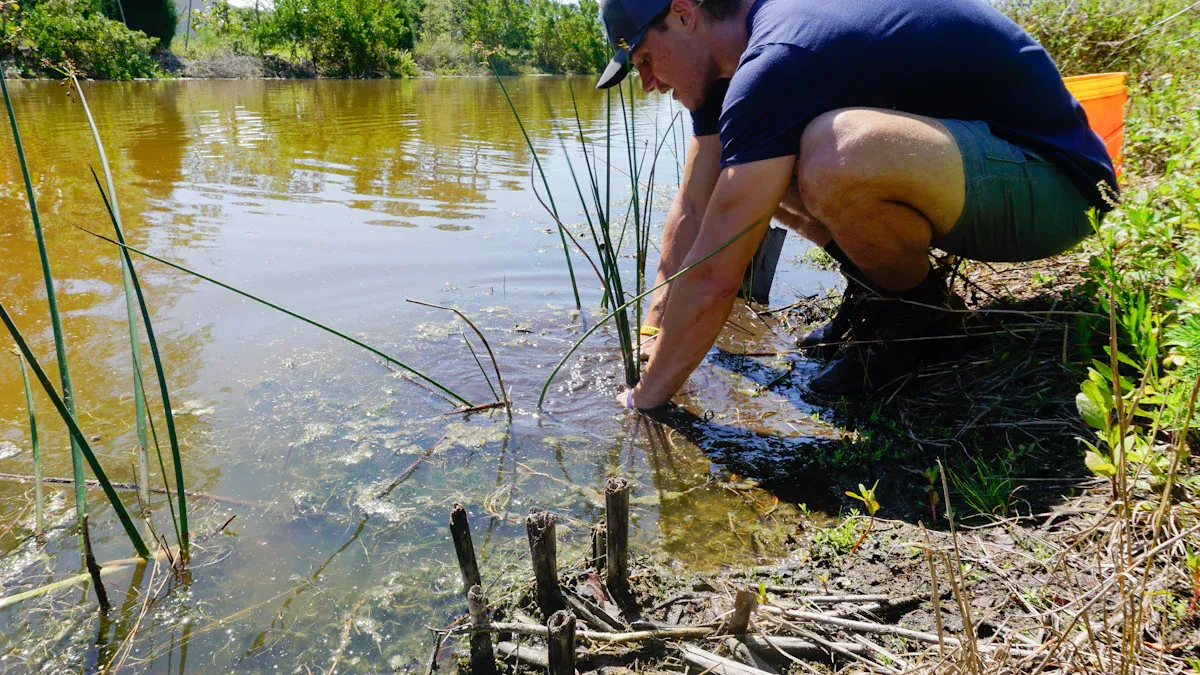
Imagine a scene like this: after a rainstorm, can the water source of remote villages be safe to drink? Has the chemical spill caused pollution to nearby rivers due to a sudden environmental accident? How can a scientific expedition team quickly evaluate the water quality of a newly discovered stream in the deep mountain jungle?
In the past, answering these questions required a long and tedious process: collecting water samples, carefully sending them back to distant laboratories, and waiting for days or even weeks for laboratory analysis. By the time the results come out, the situation may have already changed, missing the best opportunity for warning and response.
Today, technological advancements have integrated powerful laboratory analysis capabilities into a compact device that can be held with one hand - portable water quality sensors, which are fundamentally changing the way we perceive and respond to water environments, becoming an indispensable tool in the hands of field workers and emergency responders.
1、 What is a portable water quality sensor?
A portable water quality sensor is a precision electronic device that integrates optical, electrochemical, or biological sensing technologies. It can quickly and real-time perform on-site detection of various key indicators of water bodies, and usually has the following characteristics:
Compact and lightweight: small in size, light in weight, easy to carry and move, suitable for field operations.
Fast and efficient: No complex preprocessing required, detection results can be obtained within seconds to minutes, greatly improving efficiency.
Real time and intuitive: The results are directly displayed on the device's built-in screen or transmitted to smartphones and tablets via Bluetooth, achieving data visualization.
Multi functional integration: A device can often measure multiple parameters simultaneously, such as pH value, dissolved oxygen (DO), conductivity (TDS), turbidity, temperature, ammonia nitrogen, nitrate, heavy metal ions, and even specific pollutants.
Long lasting battery life: Powered by rechargeable batteries, it can meet the needs of long-term field monitoring.
2、 Why is it a 'weapon'? Analysis of Core Advantages
Mobile laboratory for field monitoring
Breaking geographical limitations: Whether it's high mountains, lakes, forests, or deserts, investigators can easily reach the site and immediately obtain data without worrying about water samples deteriorating during transportation.
Implementing grid based census: It can quickly conduct dense sampling of multiple points in an area, draw a detailed spatial distribution map of water quality, and help researchers accurately locate pollution sources or understand dynamic changes in water quality.
Improving scientific research efficiency: For field investigations in fields such as ecology, geology, and aquaculture, it can instantly determine whether the water environment is suitable for research or biological survival, and guide the next direction of work.
The 'early warning pioneer' of emergency response
Race against time, make quick decisions: After environmental pollution accidents and natural disasters (such as earthquakes and floods) occur, time is life. Portable sensors can rush to the scene in the first time, quickly screen the types, concentrations, and diffusion range of pollutants, and provide the most critical decision-making basis for whether to evacuate the masses and how to take disposal measures.
Ensuring drinking water safety: In the event of sudden water pollution or emergency water supply guarantee in disaster areas, continuous monitoring of water sources, temporary water supply points, and water treatment effects can be carried out to ensure drinking water safety and prevent the occurrence of epidemics.
Dynamic tracking of pollution clusters: It can track and monitor along the direction of water flow, real-time grasp the movement path and dilution situation of the pollution zone, and provide data support for subsequent governance evaluation.
3、 Typical application scenarios
Environmental Protection and Scientific Research: Investigation and Routine Inspection of Water Ecology in Rivers, Lakes, and Oceans.
Emergency management: on-site investigation of sudden environmental events such as chemical spills, oil pipeline ruptures, and algal blooms.
Water conservancy and water management: protection of water sources, rapid investigation of water quality in water supply networks, and monitoring of sewage treatment plant outlets.
Aquaculture: Real time monitoring of water quality changes in aquaculture ponds, timely oxygenation or adjustment of feeding to prevent risks.
Outdoor exploration and tourism: providing preliminary assessment of water source safety for hiking and camping enthusiasts (note that civilian grade equipment is for reference only and cannot completely replace boiling or purification).
4、 Challenges and Future Prospects
Despite its outstanding advantages, portable water quality sensors also face some challenges, such as possible accuracy interference in high concentration and complex water bodies, maintenance and calibration requirements for sensor probes, and cost issues for high-performance equipment.
However, the future is full of hope. With the development of nanotechnology, artificial intelligence (AI), and the Internet of Things (IoT), the next generation of portable sensors will become more intelligent, accurate, and powerful. We can foresee:
More comprehensive functions: integrating more sensing modules, one machine can handle more comprehensive analysis.
Stronger connectivity: The detection data is automatically uploaded to the cloud platform, enabling real-time sharing and big data analysis of global monitoring data, and building a smart water environment monitoring network.
Conclusion
Portable water quality sensors are like tireless water quality "detectives", bringing analysis work that could only be done in the laboratory to any water edge that requires them. It endows us with the ability to perceive the water environment on site, greatly enhancing our initiative and adaptability when exploring and responding to water crises in the wild. Undoubtedly, with the continuous popularization and deepening of technology, this "weapon" will play an increasingly important role in protecting the source of life and safeguarding ecological security.