An SD card socket connector may seem like a simple component, but the choice of SD specification version, from SD 3.0 to SD 8.0, significantly impacts connector requirements, PCB layout, and device performance. This guide helps engineers select the right SD card socket connector by explaining the differences between SD specification generations and their hardware implications.

As a manufacturer of card socket connectors, VITALCONN produces SD card sockets for all specification versions. This article draws on our engineering experience to highlight the practical differences that matter for product design. For related content, see our Micro SD card speed class guide which covers card speed ratings.

What Is an SD Card Socket Connector and Why Does Specification Version Matter?

An SD card socket connector provides the physical interface between an SD or microSD card and the host device PCB. The connector must maintain reliable electrical contact while supporting the data rates and bus modes defined by the applicable SD specification. Each new SD specification generation introduces higher speeds and new signaling modes that place greater demands on the connector and PCB routing.

The SD card socket connector must match the maximum specification your device supports. Using a connector rated only for SD 3.0 in a device designed for SD 8.0 speeds will create a bottleneck. Conversely, over-specifying the connector adds unnecessary cost. This guide helps you find the right balance.

SD 3.0 vs SD 4.0 vs SD 7.0 vs SD 8.0: Key Specification Differences

The table below summarizes the key differences between SD specification generations as they relate to SD card socket connector selection:

Specification Max Bus Speed Bus Mode Max Card Capacity Connector Impact
SD 3.0 UHS-I (104 MB/s) 1-bit / 4-bit, SDR50/SDR104 2TB (SDXC) Standard connector, 50MHz max clock
SD 4.0 UHS-II (312 MB/s) Adds UHS-II (2-lane differential) 2TB (SDXC) Extra pins for UHS-II, controlled impedance
SD 7.0 SD Express (985 MB/s) Adds PCIe/NVMe via PCIe 3.0 128TB (SDUC) PCIe-grade signal integrity required
SD 8.0 SD Express (3938 MB/s) Adds PCIe 4.0 (2-lane) 128TB (SDUC) High-speed differential pairs, minimal skew

The jump from SD 3.0 to SD 4.0 introduces UHS-II, which adds a second row of contacts on the SD card. This means the SD card socket connector must have an additional set of contact pins. The transition from SD 7.0 to SD 8.0 moves from PCIe 3.0 to PCIe 4.0, doubling the data rate but requiring even tighter signal integrity in the connector and PCB layout.

SD Card Socket Connector Types: Push-Push vs Push-Pull vs Hinge

Beyond specification version, the SD card socket connector comes in different mechanical configurations. The insertion mechanism affects user experience and reliability:

Mechanism Description Best For Durability
Push-Push Push to insert, push again to eject (spring-loaded) Consumer devices, cameras 5,000-10,000 cycles
Push-Pull Push to insert, pull to eject (friction hold) Industrial, cost-sensitive designs 10,000+ cycles
Hinge/Trap Flip-up hinge for easy card loading Compact devices, test equipment 5,000-10,000 cycles
Detent Click-in, manual release with lever Industrial, automotive 10,000+ cycles

For a detailed comparison of push-push and push-pull mechanisms, see our push-push vs push-pull card socket guide.

How to Choose the Right SD Card Socket Connector for Your Device

When selecting an SD card socket connector, consider these factors in order of priority:

  1. Target SD Specification: Determine the maximum SD specification your device must support. If your device only needs 104 MB/s, an SD 3.0 connector is sufficient. If you need SD Express speeds, the connector must support PCIe signaling with controlled impedance differential pairs.
  2. Card Format: Full-size SD and microSD require different connectors. Some devices support both via a combo socket. The SD card socket connector must match the card form factor your device accepts.
  3. Card Detection: Most connectors include a card detection (CD) switch and write-protect (WP) switch. Verify these switches match your controller requirements. Some high-speed designs eliminate the WP switch to simplify signal routing.
  4. Mounting Type: Surface mount (SMT) is standard for most designs. Through-hole mounting provides better mechanical strength for applications subject to vibration. Consider the connector footprint and panel cutout requirements.
  5. Operating Environment: For industrial or automotive applications, select connectors rated for -40°C to +85°C with vibration-resistant contact design. Gold-plated contacts (minimum 30 microinches) are recommended for reliable long-term contact.

Understanding card speed ratings is also important. See our Micro SD card speed class guide for details on Speed Class, UHS Speed Class, and Video Speed Class ratings.

💡 Tip: For devices targeting SD 7.0 or SD 8.0, request S-parameter data from the SD card socket connector manufacturer. This data should include insertion loss, return loss, and crosstalk measurements.

SD Card Socket Connector Signal Integrity Considerations

At SD Express speeds (985 MB/s for SD 7.0, 3.9 GB/s for SD 8.0), the SD card socket connector becomes a critical signal integrity component. Key considerations include:

  • Controlled impedance: PCIe differential pairs must maintain 85 ohms (±10%) through the connector
  • Insertion loss: Connector insertion loss should be below -1 dB at the maximum operating frequency
  • Crosstalk: Adjacent signal pins must maintain adequate crosstalk isolation, typically below -30 dB
  • Contact length: Shorter contact paths reduce parasitic inductance and capacitance
  • Ground structure: Adequate ground pins and shielding within the connector are essential for high-speed signaling

Common SD Card Socket Design Issues and Troubleshooting

Based on our experience supporting customer designs, common SD card socket connector issues include:

  • Intermittent card detection due to insufficient CD switch debounce or poor contact pressure
  • Signal integrity failures at UHS-II or SD Express speeds due to connector not rated for those specifications
  • Card ejection failures in push-push mechanisms due to spring fatigue or contamination
  • Contact corrosion in humid environments due to insufficient gold plating thickness
  • Mechanical failure from excessive card insertion force or misaligned PCB mounting

For cross-reference alternatives to premium brand card sockets, see our card socket cross-reference guide with pin-to-pin replacements.

VITALCONN SD Card Socket Connector Solutions

VITALCONN manufactures SD card socket connectors for all specification versions, from SD 3.0 through SD 8.0. Our product range includes full-size SD, microSD, and combo sockets in push-push, push-pull, and hinge configurations. All connectors feature gold-plated contacts, card detection switches, and are available in commercial and industrial temperature grades.

⚠ Important: To explore our card socket connector products, including datasheets and cross-reference options, visit our product page. For cross-reference alternatives, visit our ARP cross-reference platform.

Frequently Asked Questions (FAQ)

What is the difference between SD 3.0 and SD 7.0 card socket connectors?
SD 3.0 connectors support up to 104 MB/s using UHS-I bus mode. SD 7.0 connectors add SD Express support using PCIe 3.0 signaling, enabling speeds up to 985 MB/s. The SD card socket connector for SD 7.0 requires controlled impedance differential pairs and tighter signal integrity specifications compared to SD 3.0.
Can I use an SD 3.0 socket connector with SD 7.0 cards?
Yes, SD 7.0 cards are backward compatible with SD 3.0 sockets, but data transfer will be limited to UHS-I speeds (104 MB/s). To achieve SD Express speeds, both the card and the SD card socket connector must support the SD 7.0 or higher specification.
Do I need a special connector for microSD vs full-size SD cards?
Yes. Full-size SD and microSD cards have different physical dimensions and require different socket connectors. Some devices use a combo socket that accepts both formats. The SD card socket connector specification must match the card format your device is designed to accept.
What is push-push vs push-pull in SD card socket connectors?
Push-push connectors use a spring mechanism: push to insert, push again to eject. Push-pull connectors use friction: push to insert, pull to eject. Push-push is more user-friendly for consumer devices, while push-pull is more durable and cost-effective for industrial applications.
What gold plating thickness is recommended for SD card socket contacts?
For commercial applications, 30 microinches of gold over nickel is standard. For industrial or humid environments, 50 microinches provides better corrosion resistance. Always verify the gold plating specification in the SD card socket connector datasheet.
Ready to Find the Right SD Card Socket Connector?
Explore VITALCONN's full range of SD card socket connectors or request free samples for your next project.
Explore Card Socket Products Request Samples

When comparing SFP cage vs SFP+ cage, the most important fact is this: the mechanical cage is physically identical, but the electrical specification differs. Both use the same 20-pin connector footprint, the same cage dimensions, and the same module form factor. The difference lies in the data rate — SFP supports up to 4.25 Gbps, while SFP+ supports up to 10 Gbps and beyond. This means an SFP+ cage can accept SFP modules, but not all SFP cages are designed to handle the higher-speed signals that SFP+ requires. This guide explains the technical, mechanical, and electrical differences to help engineers select the right SFP cage connector for their application.

For networking equipment manufacturers, this distinction matters at the PCB design stage. The SFP cage connector serves as the mechanical and electrical interface between a pluggable optical or copper transceiver module and the host circuit board. Getting the cage selection wrong can lead to signal integrity failures, EMI compliance issues, or mechanical incompatibility with the modules your customers need to use.

VITALCONN Electronics manufactures SFP and SFP+ cage connectors for networking switches, routers, and data center equipment. This guide synthesizes our engineering team's design experience with the SFF-8472 and SFF-8083 specification requirements to provide practical, application-focused guidance. For a complete product overview, start with our Ultimate Guide to SFP Cage Connectors.

Mechanical Compatibility: Are SFP and SFP+ Cages Identical?

Yes — mechanically, the SFP cage and SFP+ cage are the same. Both follow the SFF (Small Form Factor) committee specifications for the cage and connector footprint:

Parameter SFP Cage SFP+ Cage Difference?
Connector Pin Count 20 pins 20 pins No difference
Cage Width 13.6 mm 13.6 mm No difference
Cage Height 8.5 mm 8.5 mm No difference
PCB Footprint SFF-8083 SFF-8083 No difference
Module Insertion Hot-pluggable Hot-pluggable No difference
EMI Spring Fingers Standard Standard or enhanced SFP+ may use enhanced EMI
Thermal Management Basic Often enhanced SFP+ modules run hotter

This mechanical compatibility means that an SFP module can be inserted into an SFP+ cage, and vice versa. The physical fit is identical. However, just because a module fits does not mean it will work correctly — the host board's electrical design must support the module's data rate.

SFP Cage vs SFP+ Cage: Electrical Specification Differences

The critical difference between SFP and SFP+ is electrical. While the cage connector is mechanically the same, the PCB design, signal routing, and component selection around the cage determine whether the system can handle SFP+ data rates:

Parameter SFP SFP+ Impact on Cage/PCB Design
Max Data Rate 4.25 Gbps 10 Gbps (10.5 Gbps with extended) SFP+ requires tighter impedance control
Signal Type Single-ended or differential Differential only SFP+ demands differential pair routing
PCB Trace Impedance 100 ohm ±10% 100 ohm ±5% SFP+ requires tighter tolerance
Maximum Trace Length Up to 4 inches Preferably under 2 inches SFP+ needs shorter high-speed traces
EMI Shielding Standard Enhanced recommended SFP+ cages often need additional EMI tabs
Thermal Dissipation 1.5W typical 1.5W - 3.5W typical SFP+ cages may need heatsink options
Jitter Tolerance Less stringent Stricter (SFF-8431) SFP+ PCB layout must minimize jitter

For PCB designers, this means that an SFP cage connector designed for SFP data rates may not perform adequately at SFP+ speeds without proper signal integrity engineering. The cage itself does not limit the speed — the PCB layout, connector contact geometry, and EMI shielding do.

Can I Use an SFP Module in an SFP+ Cage? (And Vice Versa)

This is one of the most frequently asked questions about SFP cage vs SFP+ cage compatibility. The answer depends on the direction:

SFP Module in SFP+ Cage: Yes (Backward Compatible)

SFP+ cages are designed to be backward compatible with SFP modules. An SFP module will physically fit and electrically function in an SFP+ cage. The host equipment typically detects the module type through the I2C interface (A0/A2 memory pages) and adjusts its data rate accordingly. This is standard practice in networking equipment — a 10G SFP+ switch port will accept a 1G SFP module.

SFP+ Module in SFP Cage: Maybe (Depends on PCB Design)

Physically, an SFP+ module will fit into an SFP cage. Electrically, it depends on whether the host PCB was designed to support 10G signals. If the PCB traces are too long, impedance is not controlled tightly enough, or EMI shielding is insufficient, the SFP+ module may experience signal integrity problems even though it fits mechanically.

💡 Best Practice: Design the PCB for SFP+ from the start, even if current products only use SFP modules. This future-proofs the design and avoids costly PCB respins when upgrading to SFP+. For a deeper comparison of the modules themselves, see our SFP vs SFP+ comparison.

SFP+ Cage EMI Shielding and Thermal Management Considerations

Because SFP+ modules operate at 10 Gbps, they generate more high-frequency EMI and more heat than SFP modules. The cage connector design must account for both:

EMI Shielding

SFP+ cages often feature enhanced EMI spring fingers that provide 360-degree contact between the module shell and the cage. These spring fingers create a continuous EMI gasket that prevents high-frequency radiation from escaping through the module-cage interface. Standard SFP cages may have fewer or less aggressive EMI fingers, which can be adequate at 4.25 Gbps but insufficient at 10 Gbps.

Thermal Management

SFP+ modules dissipate more power (up to 3.5W for some 10G copper modules) compared to SFP modules (typically 1-1.5W). The cage must provide adequate thermal conduction from the module to the PCB or chassis. Options include:

  • Thermal pads between module and cage for conductive cooling
  • Cages with integrated heatsink fins for convective cooling
  • PCB copper pours under the cage for thermal spreading
  • System-level airflow design directing air across the cage

For a comprehensive guide on SFP cage thermal design including heatsink selection and PCB thermal management, see our SFP Cage EMI Shielding guide which covers EMI finger design, shielding effectiveness testing, and thermal management strategies.

How to Choose: SFP Cage vs SFP+ Cage Selection Guide

When selecting an SFP cage connector for your PCB design, consider these factors:

  1. Current and Future Data Rate: If you need 10G now or may need it within the product lifecycle, design for SFP+ from the start. The cost difference is minimal, and it avoids future PCB respins.
  2. EMI Shielding Level: For 10G applications, select cages with enhanced EMI spring fingers. Verify the number and geometry of EMI contacts in the datasheet.
  3. Thermal Requirements: Calculate the maximum module power dissipation and ensure the cage can handle it. Add thermal pads or select cages with integrated heatsinks for high-power modules.
  4. Port Configuration: SFP/SFP+ cages are available in 1x1 (single port), 1x2, 1x4, and 1x6 configurations. Higher-density configurations require careful EMI and thermal planning.
  5. Mounting Type: Choose between SMT (surface mount) and press-fit based on your assembly process. Press-fit cages eliminate soldering but require compatible PCB hole plating.

For detailed guidance on SFP cage types, mounting options, and selection criteria, refer to our SFP cage types selection guide which covers port configurations, mounting methods, and application-specific recommendations. For the trade-offs between mounting methods, see our Press-Fit vs Solder SFP cage comparison.

Beyond SFP vs SFP+: SFP28 and QSFP Considerations

While SFP and SFP+ are the most common, newer standards have emerged for higher data rates:

Standard Max Data Rate Cage Type Module Application
SFP 4.25 Gbps SFP cage (20-pin) 1G Fibre Channel, 1G Ethernet
SFP+ 10 Gbps SFP+ cage (20-pin, same footprint) 10G Ethernet, 8G/16G Fibre Channel
SFP28 25 Gbps SFP28 cage (20-pin, enhanced SI design) 25G Ethernet, 32G Fibre Channel
QSFP+ 40 Gbps QSFP+ cage (38-pin, wider) 40G Ethernet, InfiniBand
QSFP28 100 Gbps QSFP28 cage (38-pin, enhanced) 100G Ethernet

SFP28 uses the same mechanical footprint as SFP and SFP+ but requires even tighter signal integrity engineering. The cage connector must be designed for 25 Gbps per lane, with controlled impedance, minimal crosstalk, and enhanced EMI shielding. QSFP cages are physically wider and have 38 pins, supporting four high-speed lanes.

Frequently Asked Questions (FAQ)
Is an SFP+ cage physically different from an SFP cage?
No. Both use the same 20-pin connector, the same cage dimensions (13.6mm x 8.5mm), and the same PCB footprint (SFF-8083). The mechanical interface is identical. The difference is in the electrical specification — SFP+ cages are designed and tested to support 10 Gbps signal integrity, which requires tighter PCB trace impedance control and enhanced EMI shielding.
Can I plug an SFP module into an SFP+ port?
Yes. SFP+ ports are backward compatible with SFP modules. The host equipment detects the module type via the I2C interface and adjusts the data rate accordingly. This is standard practice — most 10G switch ports accept 1G SFP modules.
Can I plug an SFP+ module into an SFP port?
Physically, yes — the module will fit. Electrically, it depends on the host PCB design. If the PCB was designed with SFP+ signal integrity requirements (controlled impedance, short traces, proper EMI shielding), it may work. If the PCB was only designed for SFP data rates, the 10G signal may not pass reliably. Always design for SFP+ if you anticipate 10G upgrades.
What is the maximum data rate for SFP+ cage connectors?
SFP+ cage connectors support up to 10 Gbps (10.5 Gbps with extended reach). For 25 Gbps applications, SFP28 cage connectors are required. While SFP28 uses the same mechanical footprint, the cage and PCB design must meet stricter signal integrity requirements.
Do SFP+ cages need special EMI shielding?
SFP+ cages benefit from enhanced EMI spring fingers that provide 360-degree contact between the module shell and the cage. At 10 Gbps, the high-frequency EMI is significantly greater than at 4.25 Gbps. Enhanced EMI shielding helps pass FCC/CISPR emissions testing and prevents interference with adjacent ports in multi-port configurations.
Ready to Select the Right SFP Cage Connector?
Explore VITALCONN's full range of SFP and SFP+ cage connectors for networking switches, routers, and data center equipment, or request free samples for your next project.
Explore SFP Cage Connectors View Cross-Reference Table

Understanding USB-C connector types is essential for hardware engineers designing products that use USB Type-C. While all USB-C connectors share the same reversible, compact form factor, the internal pin configuration varies significantly. The three most common configurations are the full USB-C 24 pin, the USB-C 16 pin, and the less common 12-pin variant. These USB-C connector types differ in data speed, power delivery capability, and application suitability. Choosing the wrong pin configuration can mean the difference between a product that supports USB4 at 40Gbps and one limited to USB 2.0 at 480Mbps. This guide breaks down each type to help you select the right connector for your design.

The USB Type-C specification defines a reversible 24-pin connector, but not all products need all 24 pins. Cost-sensitive designs can use reduced-pin-count variants that sacrifice high-speed data lanes or power delivery channels in exchange for a simpler, cheaper connector. This creates a spectrum of USB-C connector types that engineers must navigate.

VITALCONN Electronics manufactures USB Type-C connectors across all pin configurations. This guide draws on our product engineering experience to provide a practical, application-driven comparison of 12-pin, 16-pin, and 24-pin USB-C connectors. For a complete overview of the technology, start with our Ultimate Guide to USB Type-C Connectors.

USB-C 24 Pin Connector: The Full-Featured Standard

The USB-C 24 pin connector is the full implementation of the USB Type-C specification. It includes all defined contacts and supports the complete range of USB-C capabilities:

Feature 24-Pin USB-C Notes
Max Data Speed USB4 / Thunderbolt 4 (40 Gbps) Supports all high-speed lanes
Power Delivery Up to 240W (48V/5A, PD 3.1) Full VBUS and VCONN support
Display Output DisplayPort Alternate Mode 4-lane DP via SBU pins
Analog Audio Audio Adapter Accessory Mode Via SBU1/SBU2 and MIC pins
Pin Count 24 (12 per side, mirrored) Redundant pins for reversibility
Typical Applications Laptops, docks, monitors, hubs Full-featured USB-C products

The 24-pin connector has 12 contacts on each side (top and bottom). Because USB-C is reversible, the pins on each side mirror each other. This means there are effectively 12 unique signal functions, each with two physical contacts (one on each orientation):

Pin Group Pins (per side) Function Required For
VBUS A4, A9, B4, B9 Power bus (4 pins, 2 per side) Power Delivery
GND A1, A12, B1, B12 Ground (4 pins, 2 per side) All USB-C
TX1+/TX1- A2, A3 High-speed TX lane 1 USB 3.x, USB4, DP
TX2+/TX2- B10, B11 High-speed TX lane 2 USB 3.x, USB4, DP
RX1+/RX1- B2, B3 High-speed RX lane 1 USB 3.x, USB4, DP
RX2+/RX2- A10, A11 High-speed RX lane 2 USB 3.x, USB4, DP
D+/D- A6, A7 USB 2.0 data USB 2.0 fallback
CC1/CC2 A5, B5 Configuration Channel All USB-C (orientation/PD)
SBU1/SBU2 A8, B8 Sideband Use DP Alt Mode, analog audio
VCONN A4/B4 (shared) Powered cable ID chip Active/e-marked cables

For products requiring USB4 or Thunderbolt 4 support, the USB-C 24 pin connector is mandatory. Reduced pin counts cannot support the full 4-lane high-speed configuration needed for 40Gbps data rates. For more on high-speed USB-C applications, see our USB4 vs Thunderbolt 4 guide which covers signal integrity, cable requirements, and connector selection for 40Gbps designs.

USB-C 16 Pin Connector: The Cost-Optimized Middle Ground

The USB-C 16 pin connector is the most common reduced-pin configuration. It removes one pair of high-speed differential lanes (TX2/RX2) while retaining USB 2.0, USB 3.0/3.1 Gen 1 (5Gbps), and basic power delivery:

Feature 16-Pin USB-C vs 24-Pin
Max Data Speed USB 3.2 Gen 1 (5 Gbps) or Gen 2 (10 Gbps, 1-lane) Reduced from 2-lane 20Gbps
Power Delivery Up to 100W (20V/5A) with proper contacts Same as 24-pin for basic PD
Display Output DisplayPort Alt Mode (2-lane, reduced) Fewer DP lanes available
Pin Count 16 (8 per side) 8 fewer pins than full 24-pin
Cost Lower Fewer contacts = lower manufacturing cost
Typical Applications Smartphones, tablets, mid-range laptops, accessories Products that don't need USB4

The 16-pin configuration is achieved by eliminating the second high-speed lane (TX2+/TX2- and RX2+/RX2-). This means the connector supports only one direction of SuperSpeed data at a time. For USB 3.2 Gen 2 (10Gbps), this is sufficient because Gen 2 uses a single lane. However, USB 3.2 Gen 2x2 (20Gbps) and USB4 (40Gbps) require both lanes and are not supported on 16-pin connectors.

Key trade-offs of choosing USB-C 16 pin:

  • Lower connector cost due to fewer contacts
  • Simpler PCB routing with fewer high-speed differential pairs
  • Sufficient for USB 3.2 Gen 1 (5Gbps) and Gen 2 (10Gbps)
  • Cannot support USB4, Thunderbolt 4, or USB 3.2 Gen 2x2
  • Reduced DisplayPort Alt Mode capability (fewer lanes)

For PCB layout details including pin assignments for both 16-pin and 24-pin configurations, see our USB Type-C pinout guide which provides complete pin maps, signal descriptions, and PCB routing recommendations.

USB-C 12-Pin Connector: The Minimal Configuration

The 12-pin USB-C connector is the most reduced configuration. It typically retains only USB 2.0 data lines (D+/D-), VBUS, GND, and the Configuration Channel (CC) pins. This configuration is used in the most cost-sensitive applications where high-speed data is not required:

Feature 12-Pin USB-C Notes
Max Data Speed USB 2.0 (480 Mbps) No SuperSpeed lanes
Power Delivery Up to 15W (5V/3A) typical Limited by contact count
Pin Count 12 (6 per side) Minimal configuration
Cost Lowest Fewest contacts, simplest tooling
Typical Applications Charging cables, basic peripherals, low-cost accessories USB 2.0 only products
DisplayPort Not supported No high-speed lanes available

The 12-pin variant is primarily found in charging-only applications or USB 2.0 peripherals where the USB-C connector is used for its reversible form factor rather than its high-speed capabilities. Examples include basic USB-C charging cables, simple input devices, and low-cost consumer electronics.

USB-C Connector Types: Side-by-Side Comparison

The following table provides a comprehensive comparison of all three USB-C connector types:

Parameter 12-Pin 16-Pin 24-Pin
Max Data Rate 480 Mbps (USB 2.0) 10 Gbps (USB 3.2 Gen 2) 40 Gbps (USB4/TB4)
High-Speed Lanes 0 1 TX + 1 RX pair 2 TX + 2 RX pairs
USB 2.0 (D+/D-) Yes Yes Yes
Power Delivery Up to 15W Up to 100W Up to 240W (PD 3.1)
DisplayPort Alt Mode No Yes (reduced, 2-lane) Yes (full, 4-lane)
Thunderbolt 4 No No Yes
USB4 No No Yes
Reversible Yes Yes Yes
Typical Cost Lowest Medium Highest
Best For Charging, USB 2.0 devices USB 3.x devices, mid-range products USB4/TB4, high-end devices

How to Choose the Right USB-C Connector Type

Selecting among USB-C connector types depends on your product's data, power, and display requirements. Here is a practical decision framework:

  1. Identify Required Data Speed: If your product needs USB4 (40Gbps) or Thunderbolt 4, you must use a 24-pin connector. For USB 3.2 Gen 2 (10Gbps), a 16-pin connector suffices. For USB 2.0 only, a 12-pin connector is adequate.
  2. Determine Power Delivery Needs: For 100W+ PD, ensure the connector has adequate VBUS contacts. 24-pin connectors have 4 VBUS pins (2 per side), providing better current capacity. 16-pin connectors can typically support up to 100W. 12-pin connectors are usually limited to 15W.
  3. Check DisplayPort Requirements: If your product needs DP Alt Mode, it requires at least a 16-pin connector. For 4-lane DP (4K@60Hz or higher), a 24-pin connector is needed.
  4. Consider Future-Proofing: Even if current requirements are modest, using a 24-pin connector allows future firmware or product updates to leverage higher speeds without a hardware redesign.
  5. Evaluate PCB Space and Cost: 24-pin connectors require more PCB routing for high-speed differential pairs. 16-pin and 12-pin connectors are simpler to route and lower cost.

For additional guidance on matching connector capability to environmental needs, see our USB-C connector selection guide and the waterproof USB Type-C guide for harsh-environment designs.

USB-C Connector Types and Signal Integrity Considerations

The pin count of a USB-C connector directly affects signal integrity design. Higher pin counts mean more high-speed differential pairs, which require careful PCB routing:

Signal Integrity Factor 12-Pin 16-Pin 24-Pin
High-Speed Differential Pairs 0 2 (1 TX + 1 RX) 4 (2 TX + 2 RX)
Impedance Control Required No (USB 2.0 only) Yes (90-100 ohm differential) Yes (90-100 ohm differential, tighter)
ESD Protection Diodes Minimal Required on high-speed lanes Required on all high-speed lanes
EMI Shielding Basic Recommended Mandatory for 10Gbps+
PCB Layer Count 2-layer possible 4-layer recommended 4-6 layer recommended

For 24-pin connectors operating at USB4 or Thunderbolt 4 speeds (40Gbps), signal integrity engineering becomes critical. PCB trace length, via design, reference plane continuity, and connector footprint all impact whether the design can pass USB-IF compliance testing.

Frequently Asked Questions (FAQ)

What is the difference between 16-pin and 24-pin USB-C connectors?
The USB-C 16 pin connector has one pair of high-speed differential lanes (one TX and one RX pair), while the 24-pin connector has two pairs. This means 16-pin supports up to USB 3.2 Gen 2 (10Gbps, single lane), while 24-pin supports USB4 and Thunderbolt 4 (40Gbps, dual lane). The 16-pin connector is lower cost and simpler to route, but cannot support the highest USB-C data rates.
Can a 16-pin USB-C port charge at 100W?
Yes, if the connector is designed with adequate VBUS contacts and the power delivery controller supports it. The 16-pin configuration retains VBUS, GND, and CC pins, which are all that's needed for USB Power Delivery negotiation. However, the actual current capacity depends on the connector's contact design and PCB trace width, not just the pin count.
Are all USB-C cables 24-pin?
No. USB-C cables come in different configurations. Full-featured cables (supporting USB4/TB4) use 24-pin connectors on both ends. Many consumer charging cables use 16-pin or even 12-pin connectors to reduce cost. Always check the cable's rated speed and power — a USB 2.0 USB-C cable may have fewer pins than a USB4 cable despite using the same form factor.
Can I use a 24-pin USB-C module on a 16-pin PCB footprint?
Physically, a 24-pin USB-C connector will fit into the same PCB cutout as a 16-pin connector (the mechanical outline is the same). However, the PCB must have pads for all 24 pins. If the PCB was only designed for 16 pins, the extra 8 pins will have no pads to solder to, and the high-speed lanes they carry will be unconnected. Always match the connector pin count to the PCB footprint design.
Which USB-C connector type do I need for DisplayPort?
For DisplayPort Alternate Mode, you need at least a 16-pin connector. This supports 2-lane DP (sufficient for 4K@30Hz). For 4-lane DP (4K@60Hz or higher), you need a 24-pin connector. The 12-pin connector does not support DisplayPort at all because it lacks high-speed data lanes.
Ready to Choose the Right USB-C Connector?
Explore VITALCONN's full range of USB Type-C connectors across all pin configurations, or request free samples for your next project.
Explore USB-C Connectors View Cross-Reference Table

The USB4 vs Thunderbolt debate confuses many product designers because both standards use the same USB Type-C connector, yet they differ significantly in capabilities, certification requirements, and hardware demands. This article clarifies the USB4 vs Thunderbolt comparison from a connector hardware perspective, helping you choose the right USB Type-C connector for your product.

As a USB Type-C manufacturer, VITALCONN frequently receives questions about whether a standard USB-C connector can support USB4 and Thunderbolt 4. The short answer is yes, but the connector must meet specific signal integrity and mechanical requirements. This article explains those requirements in detail.

What Is the Difference Between USB4 and Thunderbolt 4?

In the USB4 vs Thunderbolt comparison, the key distinction lies in certification and minimum performance guarantees. USB4 is a specification published by the USB Implementers Forum (USB-IF), while Thunderbolt 4 is an Intel certification program built on top of USB4. The table below summarizes the differences:

Specification USB4 (Gen 3x2) Thunderbolt 4
Max Data Rate 40 Gbps 40 Gbps
Minimum Required Speed 20 Gbps (USB4 Gen 2x2) 32 Gbps (PCIe minimum)
USB-C Connector Yes (required) Yes (required)
Power Delivery Up to 100W Minimum 100W (host)
Dual 4K Display Optional Required
PCIe Tunneling Optional Required
Hub Daisy-Chain Not required Required (minimum 2 ports)
Wake from Sleep Not required Required
Certification Body USB-IF Intel

The USB4 vs Thunderbolt distinction matters because Thunderbolt 4 guarantees features that USB4 only makes optional. For product designers, this means Thunderbolt 4-certified devices require higher-quality connectors and PCB layouts to pass certification testing.

USB4 vs Thunderbolt 4: Do They Use the Same USB-C Connector?

Yes. Both USB4 and Thunderbolt 4 use the standard USB Type-C connector defined by the USB-IF specification. The 24-pin USB-C connector is the physical interface for both. However, the connector must meet stricter signal integrity requirements to support 40 Gbps data rates. For pin-level details, see our USB Type-C pinout guide.

The USB4 vs Thunderbolt comparison from a connector perspective comes down to three factors: high-speed differential pair routing, EMI shielding, and mechanical robustness. A connector that works fine for USB 2.0 (480 Mbps) may fail signal integrity tests at 40 Gbps. Key connector requirements include:

  • Controlled impedance differential pairs (85 or 90 ohms) for TX/RX lanes
  • Minimal intra-pair skew (typically <5ps) to maintain signal integrity at 20 GHz
  • Shielded connector housing with proper grounding tabs for EMI containment
  • Gold-plated contacts (minimum 30 microinches) for reliable high-speed signal transmission
  • Rated for minimum 10,000 mating cycles per USB-IF specification

USB4 Connector Hardware Requirements: What Changes at 40 Gbps?

When evaluating the USB4 vs Thunderbolt connector requirements, designers must understand that 40 Gbps data rates push the physical layer to its limits. The connector PCB footprint, via design, and trace routing all become critical. Here are the specific connector-level requirements:

Signal Integrity

The connector must maintain differential impedance of 85 ohms (±10%) across the mated interface. Crosstalk between adjacent differential pairs should be below -30 dB at 10 GHz. Connector manufacturers must provide S-parameter data including insertion loss, return loss, and crosstalk measurements.

EMI Shielding

At 40 Gbps, EMI emissions increase significantly. The USB-C connector must have a metal shield with 360-degree grounding to the PCB ground plane. Inadequate shielding leads to both radiated emissions failures and susceptibility to external interference.

Power Delivery

USB4 and Thunderbolt 4 support Power Delivery up to 100W (20V/5A). The VBUS and GND contacts in the USB-C connector must handle 5A continuous current without excessive temperature rise. Contact resistance must be low enough to prevent thermal issues.

For a deeper understanding of USB-C power delivery capabilities, see our Ultimate Guide to USB Type-C Connectors.

Choosing Between USB4 and Thunderbolt 4 for Your Product Design

The USB4 vs Thunderbolt decision should be driven by your product requirements and target market:

Use Case Recommended Standard Connector Consideration
Consumer laptop / tablet USB4 (sufficient for most users) Standard shielded USB-C, 40Gbps rated
Professional workstation Thunderbolt 4 (guaranteed dual 4K) Premium shielded USB-C, certified
Docking station / hub Thunderbolt 4 (daisy-chain required) High-quality USB-C with reinforced shield
External GPU enclosure Thunderbolt 4 (PCIe tunneling) Low-loss USB-C, minimal trace length
Industrial device USB4 (cost-effective) Industrial-grade USB-C, wide temp range
Waterproof device Either (depends on use case) See our waterproof USB-C guide

For waterproof applications, see our waterproof USB Type-C guide for IP67/IP68 rated connector options.

USB4 vs Thunderbolt: Cost and Certification Implications

Thunderbolt 4 certification requires additional testing and licensing fees paid to Intel. USB4 certification through USB-IF is generally less expensive and has broader industry support. From a connector cost perspective, both standards require similar hardware, but Thunderbolt 4 designs tend to use premium-grade connectors to ensure compliance margin.

When sourcing USB Type-C connectors for USB4 or Thunderbolt 4 designs, verify that the manufacturer provides full S-parameter data, TDR (Time Domain Reflectometry) measurements, and eye-diagram test results. VITALCONN provides these technical documents for all high-speed USB-C connectors.

VITALCONN USB-C Connector Solutions for USB4 and Thunderbolt 4

VITALCONN manufactures USB Type-C connectors rated for USB4 and Thunderbolt 4 applications, featuring 24-pin configurations, shielded housings, and gold-plated contacts. Our connectors undergo 100% electrical testing and are backed by comprehensive datasheets including S-parameters.

For cross-reference alternatives to premium brand USB-C connectors, visit our USB Type-C cross-reference guide with 26 pin-to-pin replacements.

Frequently Asked Questions (FAQ)
Is USB4 the same as Thunderbolt 4?
No. In the USB4 vs Thunderbolt comparison, USB4 is the underlying specification, while Thunderbolt 4 is a stricter certification built on USB4. Thunderbolt 4 guarantees minimum 32 Gbps PCIe speed, dual 4K display support, and 100W power delivery, while USB4 makes some of these features optional.
Can a regular USB-C cable support USB4 and Thunderbolt 4?
No. USB4 and Thunderbolt 4 require cables and connectors rated for 40 Gbps. Standard USB 2.0 cables with USB-C connectors only support up to 480 Mbps. Always check the cable and connector specifications for 40 Gbps / USB4 / Thunderbolt 4 compatibility. See our USB Type-C pinout guide for pin configuration details.
Do I need a special USB-C connector for Thunderbolt 4?
The USB-C connector itself is the same physical interface. However, it must meet stricter signal integrity requirements. The connector manufacturer should provide S-parameter data confirming 40 Gbps capability. VITALCONN offers USB-C connectors rated for USB4 and Thunderbolt 4 applications.
What is the maximum cable length for USB4 and Thunderbolt 4?
For passive copper cables, the maximum length is 0.8 meters for 40 Gbps operation. Active cables can extend this to 1-2 meters. Optical cables can reach longer distances. The connector quality at both ends affects the maximum reliable distance.
Does USB4 vs Thunderbolt 4 matter for industrial applications?
For most industrial applications, USB4 provides sufficient performance at lower cost. Thunderbolt 4 certification adds value when you need guaranteed dual-display support, daisy-chaining, or compatibility with Thunderbolt 3 peripherals. Evaluate your specific use case rather than defaulting to the higher standard.
Need USB4 or Thunderbolt 4 USB-C Connectors?
Explore VITALCONN's full range of high-speed USB Type-C connectors or request free samples for your next product design.
Explore USB-C Connectors Request Samples

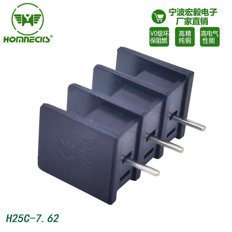
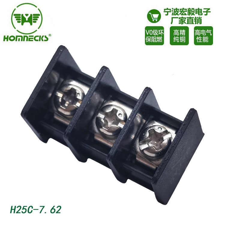
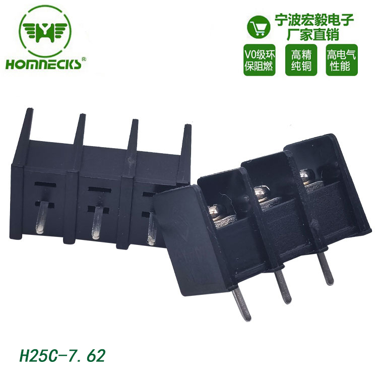
barrier terminal blocks

For industrial equipment and control cabinet wiring, safety and stable power transmission are always the top priorities.

On high-power equipment and complex wiring systems, ordinary terminal blocks often bring hidden safety risks. This is why most field engineers prefer barrier terminal blocks for heavy-duty projects.

These terminals feature independent physical barrier walls between every wiring position. This simple but effective structure is specially designed for high-current scenarios. It greatly avoids short-circuit faults and improves the overall safety of equipment power circuits.

Single-row barrier terminals

What Makes Barrier Terminal Blocks Different from Ordinary Terminals

Barrier terminal blocks are also known as American-style terminal strips. They adopt screw fastening connection methods. Every terminal point is separated by raised insulating barriers.

In actual on-site wiring, loose copper wire strands are very common during wire crimping and assembly. These tiny metal scraps easily touch adjacent terminals and cause short circuits after long-term equipment vibration.

The independent insulating barriers solve this practical problem perfectly. They physically isolate each circuit. This structure effectively cuts off the risk of cross-contact between wiring points.

PCB barrier terminal blocks

Core Advantages of Barrier Terminal Blocks in Industrial Wiring

1. Higher Electrical Safety for Cabinet Wiring

The biggest advantage of PCB barrier terminal blocks is their integrated isolation barriers.

These barriers increase the creepage distance and electrical clearance between live parts. For high-voltage industrial equipment, sufficient insulation distance is essential. It keeps the circuit stable and safe during long-time operation, fully meeting industrial electrical safety standards.

In actual cabinet assembly, this design also reduces arc discharge and electric leakage risks caused by dense wiring.


2. Reliable High-Current Bearing Capacity

Miniature PCB connectors are only suitable for low-current signal transmission. They cannot bear long-term high-power load.

Barrier terminal blocks use thickened pure copper conductive contacts and reinforced screw structures. The contact is tight and stable. It does not loosen easily under continuous high current.

For industrial power lines and motor drive wiring, these terminals avoid overheating and burnout problems. They are the most practical choice for main power connection of mechanical equipment.


3. Tough Structure for Harsh Working Conditions

Most industrial control devices work in environments with vibration, dust and temperature changes.

Barrier terminal blocks are built with thick flame-retardant plastic shells and high-strength locking screws. The overall structure is sturdy and wear-resistant. It can adapt to long-term on-site use and repeated wiring maintenance.

Most models support optional transparent protective covers. In field application, this cover can prevent staff from accidentally touching live wires during debugging. It also blocks dust and metal debris from falling into the wiring gaps, extending the service life of terminal connections.

PCB connectors

Common Industrial Application Scenarios

Barrier terminal blocks are widely used in equipment that requires high safety and stable power supply:

  • Power equipment: UPS uninterruptible power supply, switching power supply equipment
  • Industrial control: Heavy machinery control cabinets, motor driver equipment
  • Household electrical appliances: Large white household appliances that require stable mains connection
  • Transportation industry: Automotive power distribution panels, railway electrical control systems


How to Choose Suitable Barrier Terminal Blocks for Your Equipment

Engineers need to select terminals according to actual project design and cabinet layout. Here are the key selection points:

Single Row vs Double Row Terminals

Single-row barrier terminals save cabinet internal space with simple wiring. They fit equipment with fewer power circuits.

Double-row designs provide more wiring points in the same installation area. They are ideal for compact control cabinets with dense circuit requirements.

Rated Current Matching

This is the most critical selection standard. Always match the terminal rated current with the equipment’s actual maximum load current.

In actual engineering experience, do not run terminals at full load for a long time. Proper current margin can effectively prevent heating failure.

Installation Mode Selection

Choose PCB mount terminals if you need direct soldering on circuit boards.

Choose panel mount terminals for external cabinet wiring and on-site assembly wiring. Flexible installation types adapt to different equipment structural designs.


FAQ for Barrier Terminal Blocks

Q1: What is the function of the transparent cover of barrier terminal blocks?

A: The transparent protective cover is a very practical on-site accessory. It prevents accidental electric contact during equipment inspection and maintenance. Meanwhile, it isolates dust, iron filings and moisture in the workshop environment. It keeps the wiring terminals clean and ensures stable electrical performance for a long time.

Q2: Can barrier terminal blocks be used for signal wiring?

A: Although these terminals are mainly designed for power distribution circuits, they are also suitable for signal wiring in special working conditions.

For equipment with severe vibration or scenarios requiring strict circuit isolation, barrier terminals can avoid signal crosstalk and loose wiring. They provide more stable connection than ordinary signal terminals in harsh industrial environments.

Q3: Do you support customized barrier terminal blocks?

A: Yes, we are a professional terminal block manufacturer. We can customize terminal pole numbers, special mounting accessories and different pin pitches according to customer project requirements.

We support non-standard size modification and structural customization to perfectly match special control cabinet and equipment design needs.

Feature

Single-Row Barrier Terminal Blocks

Double-Row Barrier Terminal Blocks

Core Strength

Space-saving footprint, simple wiring layout

Higher connection density within limited PCB/panel space

Ideal Use Case

Designs with fewer connection points, tight linear layout

Multi-circuit power distribution where board space is constrained

Assembly Characteristics

Easier individual wire access during maintenance

Denser wiring, requires careful wire routing to avoid congestion

Cost Profile

Lower unit cost for low-channel configurations

Slightly higher cost, greater value for high I/O count designs


screw-type terminal blocks

In modern manufacturing and control cabinet production, wiring efficiency directly impacts project lead time and on-site delivery. Traditional screw-type terminal blocks rely on manual screw tightening for every wire connection. For complex PCB layouts and large control panels, this repetitive work consumes massive labor hours and slows down overall assembly progress.


Screwless terminal blocks have solved this industry pain point perfectly. Powered by precision spring tension technology, they cut down on-site wiring time significantly. More importantly, they deliver far better vibration resistance and long-term connection stability compared with conventional screw terminals, making them a future-oriented wiring solution for industrial equipment.

How Do Screwless Terminal Blocks Work?

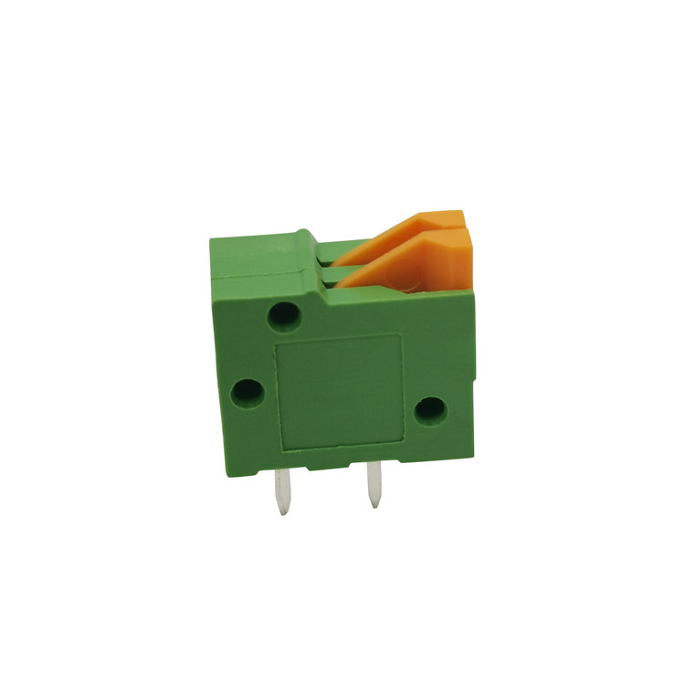
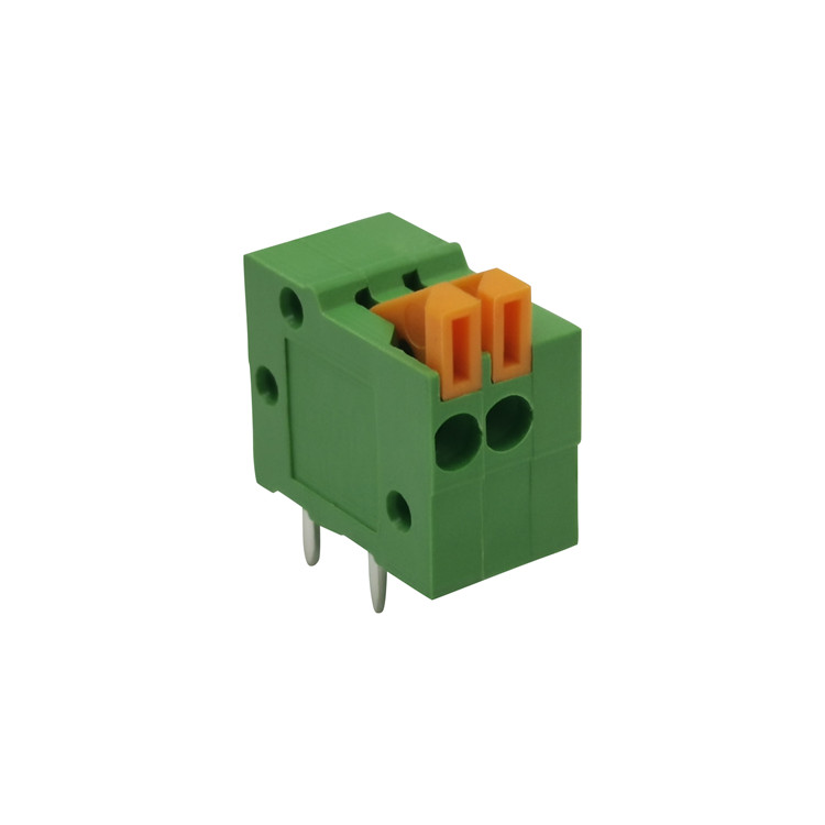
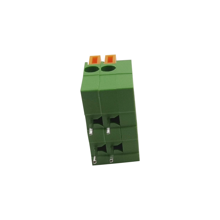
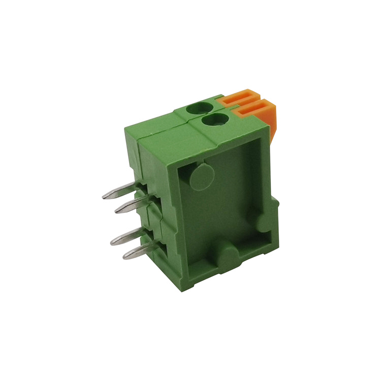
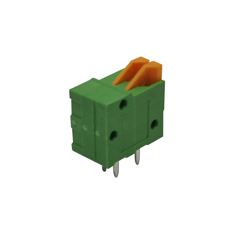
Screwless terminal blocks, also known as spring terminal blocks or push-in terminal blocks, eliminate the traditional screw fastening structure entirely. They adopt high-strength stainless steel spring components as the core clamping structure.


During on-site wiring, operators only need to insert stripped wires into the terminal holes. The built-in spring will automatically apply stable, constant pressure to lock the wire tightly against the conductive strip. This realizes fast, tool-free wiring and creates a reliable conductive connection.

push-in screwless terminals

Why Upgrade to Screwless Wiring Technology?

Most cabinet manufacturers and equipment engineers switch to screwless terminals for three core practical benefits, which address the most common pain points of traditional wiring:


1. Dramatically Faster On-Site Assembly

Speed is the biggest advantage of push-in screwless terminals. Traditional screw terminals require aligning wires, tightening screws, and checking fastening tension one by one — a tedious process for mass production.

Screwless terminals support direct wire pushing without any tools. Field test data from our assembly teams shows this solution reduces wiring time by up to 50%. It greatly improves production efficiency for batch control cabinet assembly and equipment wiring work.


2. Zero Maintenance Long-Term Reliability

Loose wiring is one of the most common on-site equipment faults. Screw-type terminals are prone to loosening under long-term equipment vibration and alternating temperature changes. Loose contacts will cause heating, poor conduction, and even unexpected equipment shutdowns.

The spring structure of screwless terminals provides continuous dynamic clamping force. The tension stays stable all year round, no matter in high-frequency vibration environments or temperature fluctuation scenarios. Engineers do not need to re-tighten terminals during regular equipment maintenance, saving long-term after-sales labor costs.


3. Ultra-Compact Design for High-Density Layout

Screw terminals require reserved space for screw heads and tool operation, which limits PCB layout density. SMD screwless terminal blocks remove bulky screw structures completely. They feature an ultra-low profile and ultra-small footprint.

This compact design is ideal for high-density PCBs, mini control devices, and LED lighting equipment with limited internal space, helping designers optimize cabinet and product structure layout.


Screwless vs Screw Terminal Blocks: Core Performance Comparison

To help engineers quickly select the right terminal blocks for project design, we sorted out a practical on-site performance comparison of the two mainstream wiring solutions:


Comparison Item
Screwless Terminal Blocks
Traditional Screw Terminal Blocks
Wiring Speed
Fast, tool-free push-in installation, 50% time saved
Slow, requires manual screw tightening for each wire
Vibration Resistance
Excellent, constant spring tension prevents loosening
Poor, screws loosen easily under long-term vibration
Subsequent Maintenance
Zero maintenance, no re-tightening required
Regular inspection and re-tightening necessary
Space Occupancy
Ultra-compact, suitable for high-density layout
Large space occupation, limited miniaturization
Service Life Stability
Long-term stable clamping force, low failure rate
Prone to aging and loose contact after long-term use


Typical Application Scenarios

Thanks to efficient wiring and stable anti-vibration performance, screwless terminal blocks have become the standard preferred solution for multiple industries:
- LED Lighting: LED drivers, modular lighting systems, and commercial lighting fixtures
- Smart Home Devices: Security alarm systems, smart thermostats, and IoT terminal equipment
- Telecommunication Equipment: Network routers, communication power supply modules, and signal transmission devices
- Vibration-Prone Machinery: Wind power equipment, elevator control systems, and rail transit electrical panels
screwless terminal blocks

Key Selection Guide for Screwless Terminal Blocks

When purchasing screwless PCB terminals for equipment projects, engineers can focus on three core indicators to avoid on-site wiring failures:
1. Operation Mode
Two mainstream types are available in the market: tool-operated and button-operated. Tool-type terminals need a flat screwdriver to pry open the spring for wire insertion and removal. Button-type terminals support fully tool-free wire release, offering more convenient on-site operation and higher maintenance efficiency.
2. Mounting Technology
Choose THT (Through-Hole Technology) terminals for traditional plug-in assembly processes. Select SMD (Surface Mount Technology) terminals for automated SMT production lines. Matching the mounting type with your production process can greatly improve assembly efficiency.
3. Wire Stripping Length
This is a detail easily ignored in on-site construction. Each screwless terminal has a standard stripping length. Strictly following the manufacturer’s recommended size ensures the spring clamps the wire core fully. Too short or too long stripping will cause poor contact or hidden safety hazards.
FAQ About Screwless Terminal Blocks
Q1: Are screwless terminal blocks safe in high-vibration environments?
Yes, they are safer and more stable than traditional screw terminals in vibration scenarios. The stainless steel spring provides continuous dynamic clamping force. It will not loosen with equipment vibration. In contrast, screw terminals will gradually lose tension over time, leading to loose connections and equipment faults.
Q2: Can stranded flexible wires be used for push-in screwless terminals?
Yes, but you need to follow standard construction specifications. For tool-free direct push-in installation, you must crimp a ferrule terminal on the stranded wire. If no ferrule is equipped, you need to press the release button or pry open the spring with a tool before inserting the bare stranded wire to ensure a firm connection.
Q3: Are screwless terminal blocks reusable?
Absolutely reusable. You can release the spring mechanism via the integrated button or a small screwdriver to pull out the wires easily. The spring structure will not be damaged after repeated disassembly and wiring. It supports multiple rewiring and maintenance operations, reducing equipment upgrade and modification costs.

Magnetic track lighting has evolved significantly over the past few years. Early magnetic track systems were often built around relatively large profiles that provided enough internal space for conductors, magnets, connections and mechanical components. Today, however, slimmer and more discreet track profiles are becoming increasingly common in architectural lighting.


The change is easy to notice. Magnetic tracks are moving from visually prominent ceiling elements toward low-profile systems that blend more naturally into the architecture. This development is closely connected with the growing preference for minimalist interiors, clean ceiling lines and lighting systems that emphasize the light itself rather than the hardware supporting it.

But making a magnetic track thinner is not simply a matter of reducing its dimensions. A smaller profile creates new challenges in electrical design, mechanical construction, thermal management and fixture integration. The real question is how to make the system smaller without sacrificing the performance and flexibility that make magnetic track lighting useful in the first place.


From Function to Minimalism

The first generation of magnetic track lighting was primarily designed around functionality. The track needed to provide power, hold lighting modules securely and allow fixtures to be installed or repositioned.

As the market developed, the role of the track changed.

Architects and lighting designers increasingly wanted the flexibility of a magnetic system without having a large visible track competing with the ceiling design. This is especially important in minimalist interiors, where even a relatively small architectural detail can affect the overall appearance of the space.

A lower-profile track creates a quieter visual element.

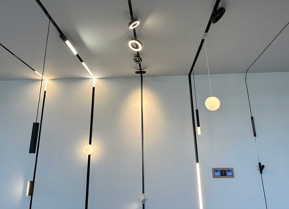
Instead of drawing attention to the lighting infrastructure, the ceiling can maintain a cleaner appearance while still providing flexible lighting positions. This is one reason ultra-slim magnetic track lighting has become increasingly relevant in contemporary residential, hospitality, retail and commercial projects.

The design philosophy is gradually moving from:

Visible lighting infrastructure

to: Minimal infrastructure with maximum lighting flexibility.

This does not mean the track has become less important. In fact, the opposite is true. The track needs to perform more functions within a smaller physical space.


What Makes an Ultra-Slim Track Possible?

Making a magnetic track thinner is an engineering challenge because the track contains much more than an external housing.

Depending on the system, the internal structure may need to accommodate electrical conductors, insulation, magnetic components, mechanical supports and connections for the lighting modules. These components have to work together within a limited cross-sectional area.

As the profile becomes smaller, the available space for each component decreases. This makes the internal arrangement more critical and increases the importance of manufacturing precision.

The track still needs to provide reliable electrical contact while maintaining appropriate insulation and mechanical strength. The magnetic connection also needs to remain secure enough for the intended fixture configuration.

Thermal management becomes another consideration. Aluminum is commonly used for magnetic track profiles because it provides structural support and can contribute to heat dissipation. When the profile becomes smaller, the available surface area and material volume may also decrease.

This means an ultra-slim system needs to be considered as a complete engineering solution:

Electrical design + mechanical structure + thermal management + fixture connection rather than simply as a smaller aluminum profile.

A successful slim design is therefore not defined by dimensions alone. It is defined by how effectively the system maintains its required performance within those dimensions.


Does Thinner Mean Better?

Not automatically.

A thinner magnetic track can provide a cleaner appearance, but the smallest possible profile is not necessarily the best choice for every project.

Different projects have different priorities. A large commercial installation may place greater emphasis on system capacity, mechanical strength and fixture compatibility, while a residential project with a minimalist ceiling may prioritize a very low visual profile.

Track size also does not directly determine lighting output.

The amount of light produced by the system depends primarily on the LED module, optical design, power and thermal performance. A smaller track can still support effective lighting when the complete system has been properly engineered.

The same applies to electrical capacity. The appropriate track profile depends on the electrical configuration, fixture load, connection method and overall system design.

For this reason, choosing a magnetic track should not start with the question:

“What is the thinnest track available?”

A better question is:

What is the thinnest track that can reliably meet the requirements of this project?

That distinction becomes increasingly important as manufacturers compete to reduce profile dimensions.

A smaller number on a specification sheet may look impressive, but long-term reliability, electrical performance, mechanical stability and fixture compatibility are ultimately more important than achieving the smallest possible profile.


Ultra-Slim, Recessed or Trimless?

The movement toward thinner magnetic track lighting is also connected with the development of different installation approaches.

An ultra-slim surface-mounted track reduces the physical and visual impact of the track while avoiding major ceiling modifications. This can be particularly useful for concrete ceilings, renovation projects and spaces where there is not enough ceiling depth for a recessed system.

A recessed magnetic track takes integration further by placing the track inside the ceiling. Only the intended visible portion remains exposed, allowing the lighting system to become part of the ceiling architecture.

A trimless magnetic track focuses even more strongly on seamless integration. By minimizing the visible transition between the track and the surrounding ceiling, the lighting channel can appear almost like a continuous architectural detail.

These approaches are different, but they respond to the same demand:

Less visible infrastructure, more visible lighting effect.

The appropriate solution depends on the ceiling construction, installation conditions, required visual effect and project budget.

For an existing concrete ceiling, an ultra-slim surface-mounted track may be more practical. For a new-build project, recessed or trimless installation may provide a more integrated result.


Why Low-Profile Design Matters Beyond Appearance

The benefit of a thinner track is not limited to aesthetics.

A lower profile can also make a surface-mounted system more practical in spaces with limited ceiling height. In a low room, a deeper track can become visually and physically noticeable, while a slimmer profile can maintain more of the original ceiling volume.

This is particularly relevant in residential interiors, apartments, corridors and commercial spaces where every millimeter of ceiling height can affect the overall feeling of the room.

A slim track can also provide an alternative when recessed installation is difficult. Instead of opening the ceiling to accommodate a deeper recessed channel, a low-profile surface-mounted system can deliver a more discreet appearance with less structural modification.

This makes ultra-slim magnetic track lighting relevant not only to new architectural projects, but also to renovation and retrofit applications.


Does a Smaller Track Limit Fixture Choices?

It can, depending on the system design.

Magnetic track lighting is valuable partly because the same track can accommodate different lighting modules. Spotlights, linear fixtures, wall washers and pendant modules can all serve different lighting functions.

As the track becomes smaller, the connection between the track and these modules becomes more challenging to engineer. The electrical contact, mechanical attachment and available installation space all become more constrained.

Therefore, an ultra-slim track should not be evaluated separately from its fixture ecosystem.

A good magnetic lighting system should maintain compatibility between the track and its intended fixtures while preserving reliable electrical and mechanical connections.

This is another reason why the smallest track is not necessarily the most advanced track. The overall system architecture matters more than one dimension.


The Trend Is Toward Integration, Not Just Thinness

It would be easy to describe the development of magnetic track lighting as a race toward thinner profiles, but the broader trend is more meaningful than that.

The industry is moving toward lighting systems that are:

  • Smaller
  • More integrated
  • More modular
  • More adaptable
  • More intelligent

Slimmer profiles reduce the visual presence of the infrastructure. Recessed and trimless systems allow the track to blend further into the ceiling. Modular fixtures provide flexibility for different lighting functions, while dimming and smart control technologies allow the same system to respond to changing lighting requirements.

In this sense, the future of magnetic track lighting is not simply about making a track thinner.

It is about making the entire lighting infrastructure less noticeable while maintaining flexibility, performance and reliability.

The ideal result is simple: the user notices the quality and direction of the light before noticing the hardware producing it.


How to Choose the Right Track Profile

Choosing a magnetic track should always begin with the project requirements rather than the profile dimension.

Consider the ceiling construction first. A concrete ceiling, suspended ceiling and newly constructed recessed ceiling may require completely different installation approaches.

Then consider the lighting requirements. The number and type of fixtures, fixture power, desired lighting effects and future layout changes can all influence the appropriate track design.

The visual objective is equally important. If the track needs to be almost invisible, an ultra-slim or recessed solution may be appropriate. If the project prioritizes higher system capacity or a wider range of fixtures, a larger profile may provide greater flexibility.

The best magnetic track is therefore not necessarily the thinnest one.

It is the one that provides the right balance between:

Profile size + performance + installation + flexibility + architectural appearance


FAQ

Why are magnetic track lights getting thinner?

The main drivers are minimalist architectural design, lower visual impact, limited ceiling depth and increasing demand for lighting systems that integrate more naturally into modern interiors.


Does a thinner magnetic track mean lower power?

Not necessarily. Track dimensions do not directly determine lighting output or system power. These depend on the electrical design, fixture configuration, LED modules and overall system architecture.


Is an ultra-slim magnetic track suitable for surface mounting?

Yes. Ultra-slim surface-mounted tracks can be especially useful where recessed installation is difficult, such as concrete ceilings, renovation projects or spaces with limited ceiling depth.


Does making a magnetic track thinner affect heat dissipation?

It can make thermal design more challenging because there is less physical space and potentially less aluminum available for heat management. The track and lighting modules therefore need to be designed and evaluated as a complete system.


Will magnetic track lighting continue to become thinner?

The trend toward lower-profile and more integrated lighting is likely to continue, but future development will not necessarily focus on thickness alone. Better integration, improved optics, smarter controls, modularity and installation flexibility are also becoming important parts of magnetic lighting design.


Magnetic track lighting combines low-voltage LED fixtures, track conductors, LED drivers, and lighting controls into one system. When flickering occurs, the cause may not be the light fixture itself. Driver compatibility, dimming method, input voltage, electrical connections, circuit loading, and voltage drop can all affect lighting stability.


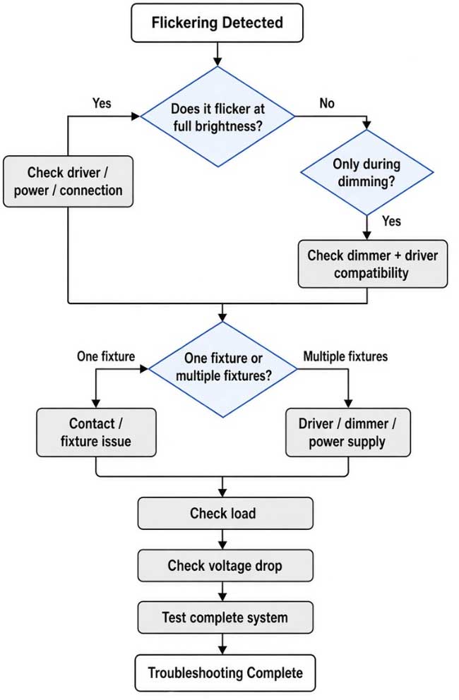
The most effective way to troubleshoot flickering is to first identify when and where it occurs. Does the flickering happen at full brightness or only during dimming? Does one fixture flicker, or do all fixtures flicker together? These details can help narrow down the cause much faster.


Common Flickering Symptoms and What to Check

Different flickering patterns can point to different parts of the lighting system.

Flickering Symptom Areas to Check First
Flickers only during dimming Dimmer and driver compatibility
Flickers mainly at very low brightness Low-end dimming performance
Flickers at full brightness Driver, power supply, or electrical connection
Only one fixture flickers Fixture, contact points, or individual driver
Several fixtures flicker together Driver, dimmer, input power, or main connection
Fixtures become dimmer toward the end of the track Voltage drop
Flickering appears after adding more fixtures Driver capacity, circuit loading, or wiring

Different performance under different input voltages

Driver and dimmer compatibility

This symptom-based approach is more useful than replacing components randomly.


1. Driver Compatibility Is One of the First Things to Check

The LED driver plays a central role in the performance of magnetic track lighting.

For a low-voltage magnetic track system, the driver must provide the appropriate output voltage and sufficient power for the connected fixtures. For example, a 24V magnetic track system requires a suitable 24V constant-voltage driver when the fixtures are designed for constant-voltage operation.

The driver should also be compatible with the required control method. A driver designed for standard on/off operation cannot automatically be assumed to perform correctly with TRIAC, 0-10V, or DALI control.

Possible symptoms of an unsuitable driver or incompatible combination include:

  • Flickering
  • Unstable dimming
  • Limited dimming range
  • Sudden shut-off during dimming
  • Uneven brightness
  • Unexpected behavior when the load changes

When investigating flicker, it is therefore important to evaluate the LED fixture and driver as a combination, rather than treating them as completely independent components.


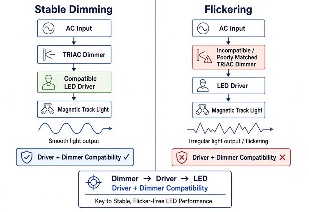
2. TRIAC Dimming Requires Driver and Dimmer Compatibility

TRIAC dimming is commonly used in residential and commercial lighting, but not every LED driver is compatible with every TRIAC dimmer.

A TRIAC dimmer modifies the AC waveform supplied to the LED driver. The driver then needs to process this changing input while maintaining stable LED output.

If the dimmer and driver are not well matched, the system may show:

  • Flickering during dimming
  • Flickering at low brightness
  • A limited dimming range
  • Sudden shut-off
  • Uneven brightness
  • Unstable operation when the dimming level changes quickly

This explains why a magnetic track light can operate normally at full brightness but perform poorly when dimmed.

For a TRIAC-dimmable magnetic track lighting project, the actual driver and intended dimmer should be tested together.


3. Why Can Input Voltage Affect Dimming Performance?

Input voltage can influence the behavior of an LED driver, particularly when phase-cut dimming is involved.

For example, a driver may show different dimming behavior when tested under 120V and 220–240V input conditions. The result also depends on the specific dimmer, driver design, connected load, and electrical conditions.

Therefore, a test performed at 220–240V with a European-market dimmer should not automatically be used to predict the performance of the same driver in a 120V North American installation.

For a North American project, the most representative test setup is:

120V input + intended US-market dimmer + specified LED driver + representative magnetic track lighting load

This does not mean that 120V provides inherently better dimming performance. It means that the lighting system should be evaluated under the same electrical conditions expected in the final installation.


4. Check the Total Electrical Load

The total connected load is another important factor.

For a 24V system, current can be estimated using:

Current = Power ÷ Voltage

For example:

200W ÷ 24V ≈ 8.33A

At the same power:

200W ÷ 48V ≈ 4.17A

This illustrates why a higher-voltage low-voltage system can carry the same power with less current.

However, total wattage is not the only consideration. The actual design should also account for:

  • Driver rated output
  • Track conductor capacity
  • Connector/contact rating
  • Track length
  • Power-feed location
  • Voltage drop
  • Wiring configuration
  • Manufacturer specifications

The maximum allowable load should therefore be determined from the specifications of the complete magnetic track system rather than applying a universal wattage limit to all magnetic tracks.


5. Voltage Drop Becomes More Important on Long Track Runs

Voltage drop occurs because electrical conductors have resistance. As current travels through the conductors, some voltage is lost.

The effect becomes more significant when:

The track is longer

The connected load is higher

The operating voltage is lower

The conductor resistance is higher

For the same power, a 24V system draws approximately twice the current of a 48V system. For example:

200W at 24V ≈ 8.33A

200W at 48V ≈ 4.17A

With the same conductor resistance, the higher current in a 24V system can result in greater resistive voltage drop.

Voltage drop does not always produce visible flickering. More commonly, it can cause reduced brightness or uneven light output, particularly toward the far end of a long track. Under certain conditions, however, the reduced voltage may contribute to unstable operation if the driver or LED load is sensitive to the available voltage.

For longer magnetic track installations, power-feed location, track length, total load, and conductor characteristics should therefore be considered together.


6. Check the Magnetic Track Electrical Contacts

Magnetic track lighting uses electrical contacts between the lighting fixture and the track. These contacts need to maintain a stable electrical connection during operation.

A poor or intermittent contact can cause unstable lighting or intermittent flickering.

When only one fixture is affected, check:

  • Fixture contact points
  • Fixture installation
  • Track surface and contact condition
  • Track connectors
  • Power-feed connections
  • Track joints

A useful troubleshooting rule is:

One fixture flickering → check the fixture and its local connection first.

Multiple fixtures flickering together → check the driver, dimmer, power input, and main track connection first.

This simple distinction can significantly reduce troubleshooting time.


7. Why Does Flickering Sometimes Appear Only at Low Brightness?

Low-level dimming can be more demanding for an LED driver than operation at full output.

When the dimming level becomes very low, the driver must maintain stable LED operation under a reduced control input or output condition. The actual minimum stable dimming level depends on the driver design and the selected control method.

If a driver and dimmer are not well matched, flickering may become noticeable near the lower end of the dimming range even though the light operates normally at higher brightness.

For this reason, dimming performance should be tested across the intended operating range:

100% → medium brightness → low brightness → minimum stable output

The minimum usable dimming level should be determined from actual testing rather than assuming that every LED system can dim smoothly to 0%.


9. A Practical Flicker Testing Process

Step 1: Establish a Baseline

Start by operating the magnetic track lighting at full brightness without dimming.

Record whether the lighting is stable before introducing any dimming or additional fixtures.


Step 2: Change One Variable at a Time

Keep the track, fixtures, and driver unchanged while testing one variable at a time, such as:

Input voltage

Dimming device

Dimming level

Number of connected fixtures

Changing several components simultaneously can make it difficult to determine which factor caused the change in performance.


Step 3: Compare Different Dimming Levels

Test the lighting at several brightness levels rather than only checking maximum and minimum output.

For example:

100% → 75% → 50% → 25% → minimum stable level

Record the point at which flickering first becomes visible.


Step 4: Compare Different Load Conditions

Start with one fixture and gradually increase the number of connected fixtures.

If the lighting remains stable with one fixture but becomes unstable as the load increases, the power supply, driver capacity, track loading, or electrical distribution should be investigated.


Step 5: Check Different Positions on the Track

Compare fixtures located near the power input with those farther away.

If the fixtures at the far end show lower brightness or different behavior, measure the voltage at different points along the track to determine whether voltage drop is contributing to the problem.


Step 6: Compare the Actual Project Conditions

Finally, reproduce the electrical conditions expected in the final installation.

This approach helps distinguish between a fixture problem, driver issue, dimming compatibility problem, load-related issue, and track-level electrical problem.


10. How to Prevent Flickering in a Magnetic Track Lighting Project

Preventing flickering during the design stage is generally easier than troubleshooting it after installation.


Match the System Voltage

Make sure the magnetic track, LED fixtures, and driver are designed for the same operating voltage.


Select the Correct Driver

Choose the driver according to its output voltage, rated power, input voltage, dimming capability, and manufacturer's specifications.


Match the Dimming Method

For TRIAC, 0-10V, or DALI projects, use a driver designed for the required control method and verify compatibility before installation.


Calculate the Total Load

Consider the total connected wattage as well as the rated capacity of the driver, track conductors, connectors, and power-feed components.


Consider Track Length and Voltage Drop

For long or high-load installations, consider voltage drop during the initial design. Power-feed location and additional feeding points may need to be evaluated according to the specific track system.


Test Before Installation

Before mass installation, test a representative configuration using the intended input voltage, driver, control device, track, and lighting load.

For dimmable projects, test the complete dimming range rather than checking only whether the lights can turn on and off.


FAQ

Is 48V better than 24V for long magnetic track lighting?

For the same power and conductor resistance, a 48V system draws less current than a 24V system. Lower current can reduce resistive voltage drop. The appropriate voltage still depends on the complete track, fixture, driver, and project design.


Why does only one magnetic track light flicker?

If only one fixture flickers while other fixtures remain stable, check the individual fixture, its electrical contacts, connector, and driver first. A local connection or fixture issue is more likely than a problem affecting the entire circuit.


How can I test a magnetic track lighting system before installation?

Use a representative setup containing the intended input voltage, LED driver, dimmer or control system, magnetic track, and expected fixture load. Test the system at full brightness and throughout the required dimming range. For longer track runs, voltage at different points along the track can also be checked.


What is the most important step when troubleshooting flickering?

Start by identifying when the flickering occurs and how many fixtures are affected. Whether the problem appears at full brightness, only during dimming, on one fixture, or across the entire track can quickly narrow down the likely cause. From there, check the driver, control method, input voltage, load, electrical connections, and voltage drop systematically.


When selecting a magnetic track lighting system for an international project, lighting performance is only one part of the decision. Certification compliance is another important factor that affects whether a product can be approved, installed, and used in different markets.

Unlike traditional lighting products, a magnetic track lighting system usually includes multiple components, including track rails, LED modules, drivers, connectors, and control devices. Each component may have different requirements depending on the target market and project specifications.

Understanding certification requirements before starting a project can help reduce approval delays, avoid product changes, and ensure smoother cooperation between manufacturers, designers, and contractors.


Why Certification Matters

Lighting products are directly connected to electrical systems, so safety compliance is a key consideration for international projects.

For distributors, contractors, and project owners, certifications provide confidence that products have been evaluated according to relevant safety standards.

Certification requirements may involve:

  • Electrical safety
  • Product construction
  • Component compatibility
  • Installation conditions
  • Regional regulations
  • Project specifications

Different countries and regions may follow different standards. A lighting product designed for one market may require additional evaluation before being used in another.


Common Certifications

The required certifications for magnetic track lighting depend on the destination market and application.


ETL Certification

For projects in the United States and Canada, ETL certification is one of the most commonly requested safety certifications for lighting products.

The ETL mark is issued by Intertek after products are tested according to applicable safety standards.

For magnetic track lighting systems, evaluation may include:

  • Electrical safety
  • Temperature performance
  • Mechanical construction
  • Component suitability
  • Installation requirements

ETL certification can help lighting products meet the expectations of North American distributors, contractors, and commercial projects.


UL Certification

UL certification is another widely recognized safety certification in North America.

Depending on the product type and application, lighting products may need to comply with relevant UL standards.

For many projects, customers may accept either UL or ETL certification depending on their specifications and local requirements.


CE Certification

For European markets, CE compliance is commonly required.

CE requirements may include:

  • Electrical safety
  • Electromagnetic compatibility (EMC)
  • Low voltage requirements
  • Environmental requirements such as RoHS

Products intended for European projects should be evaluated according to the applicable regulations.


Other Certifications

Some projects may require additional certifications depending on the country or application.

Examples include:

  • CB certification for international markets
  • FCC requirements for products with wireless communication functions
  • SAA certification for Australia and New Zealand

The correct certification depends on where the product will be installed and how it will be used.


System Components

A common misunderstanding is that only the LED fixture requires certification. In reality, a complete magnetic lighting system consists of multiple components that work together.


Track Rail

The track is not only a mounting structure. It also contains electrical conductors that deliver power to the lighting modules.

Certification considerations may include: electrical insulation, conductor design, mechanical strength, installation method.


Light Modules

Magnetic track light fixtures can include different modules, such as: spotlights, linear lights, pendant lights, wall washers, decorative fixtures. Each type may have different requirements related to electrical design, thermal management, and construction.


Drivers

The driver is one of the most important components in a magnetic track lighting system.

The selected driver affects: system safety, output voltage, power capacity, dimming performance, control compatibility.

For example, 24V and 48V magnetic track lighting systems require suitable drivers that match the fixture specifications.


Controls

Modern magnetic lighting systems increasingly support advanced control solutions, including:

  • DALI
  • 0-10V
  • TRIAC
  • Zigbee
  • Smart lighting platforms

For projects requiring smart control or tunable white lighting, the compatibility between fixtures, drivers, and control systems should be confirmed during the design stage.


ETL and Magnetic Track Lighting

ETL certification does not always mean that every possible product combination is automatically covered.

A magnetic track lighting system may include different track models, fixture types, drivers, and configurations. Certification coverage depends on the products and components that have been evaluated.

Before starting a project, it is important to confirm:

  1. Which models are included in the certification
  2. Which components are approved
  3. Which drivers are specified
  4. Whether new configurations require additional evaluation

This is especially important for customized projects where new fixture designs or electrical configurations may be introduced.


Before purchasing certified magnetic track lighting, project buyers should confirm several details.

Certification Scope

Check whether the certification applies to: complete systems, specific fixtures, track rails, drivers, accessories

Market Requirements

Certification requirements vary by country.

A product designed for North America may need different documentation compared with products intended for Europe or other regions.

Product Changes

Changes after certification may affect compliance, including: driver replacement, track structure changes, new fixture designs, electrical modifications.

Confirming these details early can help avoid delays during project approval.


Project Impact

Certification is not only a compliance requirement. It can also influence the overall project process.

For designers and contractors, certified lighting products can provide:

  • Easier project approval
  • Clear technical documentation
  • Reduced compliance risks
  • More reliable product selection

For manufacturers, maintaining consistent production is equally important because certified products need to match the approved design and components.


FAQ

Is ETL certification required for magnetic track lighting in the US?

ETL certification is commonly requested for lighting products used in US projects, especially commercial and architectural applications. The exact requirement depends on the project specifications and local regulations.


Does the driver need certification for magnetic track lighting?

The driver is an important part of the system and needs to meet applicable safety requirements. The driver specification should be confirmed together with the track and lighting modules.


Are ETL and UL the same certification?

ETL and UL are both recognized safety certification marks in North America. They are issued by different testing organizations but both indicate compliance with applicable safety standards.


What certifications are needed for magnetic track lighting in Europe?

European projects commonly require CE compliance, including applicable requirements related to electrical safety, EMC, and environmental regulations.


Do customized magnetic track lighting products need new certification?

Not always. Minor changes may be evaluated differently depending on their impact on safety performance. However, customized tracks, new fixture designs, or different electrical configurations should be reviewed before production.


This article introduces Golden Vision's 1.77-inch TFT display module, covering its key specifications, technical advantages, and typical B2B applications. It explains why Golden Vision is a trusted LCD display manufacturer and supplier for global buyers, and provides guidance on how to inquire about wholesale pricing, custom solutions, and engineering support.


When designing portable electronic devices, industrial control panels, or consumer gadgets, the display is often the most critical interface between the product and its user. For B2B buyers, sourcing the right TFT display module requires balancing size, resolution, durability, and cost—all while ensuring supply chain reliability. The 1.77-inch TFT display has emerged as a popular form factor for applications where a modest screen size still demands clear, vibrant visuals and stable operation.

AnHui Golden Vision Optoelectronic Technology Co.,Ltd, a premier LCD display manufacturer in China, offers a high-performance 1.77-inch TFT module that meets the rigorous demands of global B2B clients. Whether you are a LCD display distributor expanding your catalog, a procurement professional seeking LCD display wholesale quantities, or an OEM engineer looking for a dependable TFT display supplier, this module delivers a compelling combination of technical specifications and cost-effectiveness.


Product Overview: 1.77" TFT Display Module

Golden Vision's 1.77-inch TFT display is engineered for applications that demand clear color graphics in a compact footprint . With its transmissive working mode and RGB interface, this module is ideal for handheld devices, small-form-factor instrumentation, and embedded systems .

 
Parameter Specification Parameter Specification
Size 1.77" TFT Resolution 128RGB × 160
Working Mode Transmissive Display Area 28.03 × 35.04 mm
Appearance Size 34.7 × 46.72 × 2.2 mm Drive IC ST7735P3-G6
Viewing Angle 6 o'clock direction Interface RGB / MCU
Operating Voltage 2.8 – 3.2V Storage Temperature -30 ~ +80°C
Working Temperature -20 ~ +70°C Brightness 300 cd/m² (Min)


Key Features & Technical Advantages

1. Optimal Resolution for Small-Screen Applications

With 128RGB × 160 pixel resolution, this 1.77-inch TFT delivers crisp text, clear icons, and smooth graphical content. It strikes an ideal balance between detail and processing overhead, making it suitable for microcontroller-driven systems where memory and bandwidth are constrained.


2. ST7735P3-G6 Driver IC – Proven Reliability

The module integrates the widely adopted ST7735P3-G6 driver IC, known for its excellent compatibility with mainstream MCUs and its robust performance in mass-production environments. This driver supports RGB interface operation, enabling straightforward integration with a variety of host processors .


3. Transmissive Mode with Bright Output

The transmissive design, combined with an efficient LED backlight unit, ensures high brightness and good readability even in moderately lit indoor environments. For outdoor or high-ambient-light conditions, the module can be paired with additional optical enhancements (e.g., anti-glare or high-brightness options) upon request .


4. Compact Mechanical Footprint

Measuring just 34.7 × 46.72 × 2.2 mm, this module fits easily into space-constrained product enclosures. Its slim profile is particularly advantageous for wearable devices, portable medical monitors, and handheld test equipment .


5. Wide Operating Temperature Range

Rated for -20°C to +70°C operation and -30°C to +80°C storage, this display is engineered to perform reliably in diverse environments—from cold-chain logistics terminals to warm industrial workshop floors.


6. Customization Options Available

Golden Vision supports a range of customizations to meet specific project requirements, including:

  • Backlight brightness adjustment

  • Capacitive or resistive touch panel integration

  • FPC shape and pin-out modifications

  • Demo board availability for rapid prototyping 

All products are RoHS compliant, ensuring adherence to international environmental standards .


Typical B2B Applications

This module's versatility makes it suitable for a wide range of industries and use cases :


Industry Use Cases
Medical Devices Infusion pumps, AEDs, blood pressure monitors, ventilators
Industrial Control HMI panels, process indicators, charging stations
Automotive Aftermarket Tire pressure monitoring systems (TPMS)
Consumer Electronics IP phones, coffee machines, portable devices


Why Choose Golden Vision as Your LCD Display Manufacturer?

1. Trusted LCD Display Factory with Advanced Manufacturing

As a professional LCD display factory, Golden Vision leverages automated assembly lines, precision optical inspection systems, and stringent quality control protocols. This ensures that every 1.77-inch TFT module leaving the factory meets consistent optical, electrical, and mechanical specifications—critical for high-volume B2B orders .


2. Competitive Wholesale Pricing

For buyers seeking TFT display wholesale, Golden Vision offers factory-direct pricing that eliminates intermediary margins. Combined with flexible order quantities—from engineering samples to mass production—this makes them a preferred LCD display supplier for cost-sensitive projects without compromising on quality.


3. Comprehensive Customization & Engineering Support

Golden Vision's experienced engineering team offers tailored solutions to meet specific requirements, including touch panel integration, brightness adjustments, and interface modifications . This flexibility positions Golden Vision as a value-added TFT display manufacturer for OEM and ODM partners.


4. Reliable Supply Chain & Global Reach

With established procurement channels for key components and a robust logistics network, Golden Vision ensures stable supply even during market fluctuations. Their displays are used by industries worldwide, backed by a commitment to quality and excellent customer support .


5. Quality Certifications

Golden Vision adheres to stringent quality control processes, with products compliant with RoHS and other international standards .


Related Products from Golden Vision


Related Case Studies


Conclusion

The 1.77-inch TFT display from Golden Vision offers B2B buyers a winning combination of proven reliability, competitive pricing, and flexible customization—backed by a reputable LCD display manufacturer with a global export track record. Whether you are sourcing for a new product launch, expanding your distributor portfolio, or seeking a long-term LCD display supplier, this module deserves your consideration.

Partner with Golden Vision today to discuss your 1.77-inch TFT display requirements. Request samples, review datasheets, or schedule a technical consultation to see how our display solutions can elevate your next-generation products.


📩 Get In Touch

AnHui Golden Vision Optoelectronic Technology Co.,Ltd.
Your Trusted LCD Display Manufacturer & Supplier in China

Contact us now for wholesale pricing, custom solutions, and engineering support – we're here to power your next innovation.