Magnetic Track lighting is reshaping the way designers and homeowners approach modern interiors. Vandolite leads the industry with a focus on innovation, flexibility, and refined design. Minimalist trends now influence many spaces, and users increasingly prefer lighting solutions that do not rely on main lights. The simple structure of magnetic tracks allows seamless connection between ceilings and walls, giving strong orientation and a fresh, customizable look. Vandolite’s advanced technology and user-friendly features deliver a lighting experience that appeals to both professionals and enthusiasts.
Key Takeaways
- Magnetic Track lighting offers a sleek, modern design that fits well in minimalist and contemporary spaces.
- The system allows easy, tool-free repositioning of fixtures, giving users great flexibility to change lighting layouts anytime.
- Installation requires professional help for best results, but adjusting lights afterward is simple and quick without tools.
- Energy-efficient LED technology and smart controls help reduce electricity use and create personalized lighting moods.
- Vandolite leads with innovative, high-quality magnetic track products that suit homes, offices, retail, and galleries.

What Is Magnetic Track Lighting
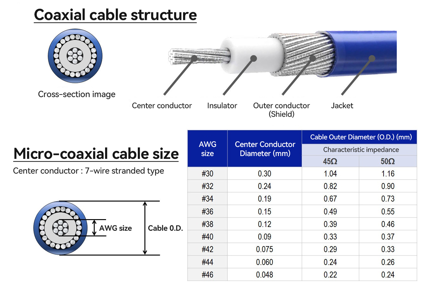
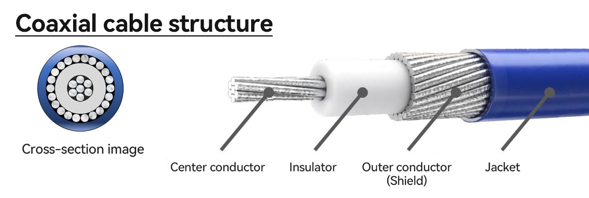
Magnetic Track lighting represents a modern approach to illumination that combines advanced engineering with sleek aesthetics. This system consists of three main components: the track, the magnetic fixtures, and the power supply. The track, often crafted from high-strength aluminum alloy, serves as both the physical support and the electrical conduit. Magnetic fixtures, such as spotlights, linear lights, pendant lights, and grille lights, attach securely to the track using strong magnets. The low-voltage power supply ensures safe and stable operation, making the system suitable for a wide range of environments.
Tip: Magnetic Track lighting systems allow users to easily reposition fixtures without tools, offering unmatched flexibility for changing layouts or highlighting specific areas.
Key materials and technologies include:
- Aluminum housing for effective heat dissipation and durability.
- Copper conductors for reliable electrical performance.
- Flame-retardant plastics for enhanced safety.
- LED light sources, reflectors, and heat sinks for optimal brightness and thermal management.
- Smart control options, such as motion sensors and dimmers, for personalized lighting experiences.
How It Works
Magnetic Track lighting operates through a combination of magnetic attraction and modular design. The track contains an iron sheet and copper conductors, enabling fixtures to adhere magnetically and receive power simultaneously. Users can slide or reposition fixtures along the track with minimal effort, adapting the lighting arrangement as needed.
| Feature |
Magnetic Track Lighting |
Conventional Track Lighting |
| Attachment Method |
Strong magnets, tool-free adjustment |
Manual buckles, requires loosening |
| Power Supply |
Low voltage DC (24V/48V), safer operation |
High voltage AC (220V), driver in fixture |
| Fixture Mobility |
Freely movable, easy to reposition |
Fixed, manual adjustment |
| Design Flexibility |
Modern, minimalist, highly customizable |
Traditional, less flexible |
Tracks resist corrosion and oxidation, even in challenging environments. Accessories like connectors and controllers support smart integration, making Magnetic Track lighting a preferred choice for both residential and commercial spaces.
Modern Design
Modern interiors demand lighting that complements clean lines and uncluttered spaces. Magnetic Track lighting stands out with its minimalist and streamlined appearance. Designers and homeowners appreciate how these fixtures blend seamlessly into ceilings and walls, reducing visual clutter. The system supports a variety of fixture types, such as spotlights, pendant lights, and linear lights, which cater to both functional and decorative needs.
- Flexibility in lighting layout allows for dynamic and multifunctional spaces.
- Sleek, contemporary designs integrate well with modern interior styles.
- The system’s aesthetic appeal enhances architectural features without drawing unnecessary attention.
The rise of Magnetic Track lighting reflects a broader trend toward visually clean, adaptable, and energy-conscious lighting solutions in both residential and commercial environments.
Flexibility and Customization
Magnetic Track lighting systems excel in flexibility and customization. The magnetic attachment mechanism enables users to reposition, replace, or reconfigure fixtures at any time. This modular approach supports multiple fixture types on a single track, allowing for tailored lighting layouts that adapt to changing needs.
Compared to traditional lighting systems, magnetic tracks offer superior ease of use. Users can adjust lighting positions without tools or complex installation steps. This makes the system ideal for spaces where frequent changes in layout or lighting focus are necessary. The ability to mix and match spotlights, linear lights, and pendants on the same track provides unmatched versatility.
The system’s adaptability ensures that lighting can evolve alongside interior design trends or functional requirements, making it a preferred choice for dynamic environments.
Easy Installation
Installation of Magnetic Track lighting requires specific skills and tools. Professional assistance is recommended to ensure optimal performance and longevity. Experts can determine the appropriate number of lights, select suitable fixtures, and install the system correctly. This attention to detail guarantees that the lighting system functions efficiently and safely.
Despite the need for expertise, the magnetic attachment simplifies the process of adding or adjusting fixtures after the initial setup. Users benefit from tool-free adjustments, which save time and reduce disruption in both residential and commercial settings.
Professional installation ensures the system’s reliability, while the magnetic design allows for ongoing flexibility and convenience.
Lighting Performance
Lighting performance remains a key advantage of Magnetic Track lighting. The system uses advanced LED technology and operates on low voltage, which significantly reduces electricity consumption. Users often notice lower electricity bills after switching to this lighting solution. The system aligns with green building standards and supports sustainable development goals.
- LED technology and low voltage operation enhance energy efficiency.
- Smart controls, such as dimmers and app-based automation, enable precise lighting management and further energy savings.
- The system allows multiple circuits on one track, supporting individual dimming and better energy management.
| Feature |
Benefit |
| LED Technology |
High brightness, low energy use |
| Low Voltage |
Increased safety, reduced power consumption |
| Smart Controls |
Customizable ambiance, automated savings |
| Modular Design |
Adaptable to various lighting needs |
Magnetic Track lighting delivers superior performance, combining energy efficiency, safety, and advanced control options for modern spaces.
Product Lines
Vandolite offers a comprehensive range of Magnetic Track lighting systems designed to meet the needs of both residential and commercial environments. Each product line features unique dimensions and design elements, allowing architects and designers to select the best fit for their projects. The Standard, Mini, and Ultra Slim tracks provide options for various space requirements, while the Linear Up-Down and Curvy tracks introduce vertical and curved lighting possibilities. Vandolite’s Belt Track & Free Lighting System stands out for its modular, flexible design, enabling users to reposition fixtures across ceilings, walls, and even desktops.
| Product Line |
Track System Size (W*H mm) |
Design Features & Notes |
| Standard |
39 x 78 |
Linear and curvy tracks available |
| Mini |
28 x 58 |
Linear and curvy tracks available |
| Ultra Slim |
28 x 29 |
Compact engineering |
| Linear Up-Down |
28 x 63/87 |
Vertical track option |
Vandolite’s magnetic connection system allows for easy installation and repositioning of fixtures. The company’s patent-protected designs and private tooling ensure exclusivity and high quality. Tracks and lamps can be customized, cut, and placed as needed, supporting a wide range of lighting layouts. Vandolite backs its products with a three-year warranty and strict quality control, providing peace of mind for users.
Technology and Quality
Vandolite invests heavily in research and development to maintain its leadership in Magnetic Track lighting technology. The company’s independent R&D team explores new optical systems, electrical designs, and structural innovations. This commitment results in lighting solutions that balance performance, aesthetics, and durability. Vandolite’s technological advancements include the Belt Track & Free Lighting System and the 10mm New Flexible PCB Magnetic Track Light System, both of which offer modularity and user-friendly installation.
- Vandolite’s R&D drives the creation of flexible, patent-protected systems.
- The 10mm system emphasizes compactness and sustainability, reducing packaging waste.
- Innovations focus on thermal efficiency and customizable lighting distributions.
- The company’s products attract clients seeking exclusive, high-performance lighting.
- Vandolite’s global presence ensures that its solutions meet diverse architectural and market demands.
Vandolite’s dedication to quality extends from raw material selection to precision manufacturing and rigorous testing. The company’s global reach and continuous innovation make it a trusted partner for projects worldwide.

Residential Spaces
Vandolite’s Magnetic Track lighting system transforms residential interiors with its adaptable design. Homeowners can easily reposition fixtures to highlight artwork, illuminate reading nooks, or create ambient lighting in living rooms and bedrooms. The system’s minimalist profile blends with modern décor, making it a popular choice for apartments and houses seeking a clean, uncluttered look. Many users appreciate the ability to mix spotlights and linear lights on a single track, allowing for both focused and general illumination. In kitchens, adjustable fixtures provide task lighting over counters, while in hallways, the system offers a seamless way to guide movement and enhance safety.
Homeowners value the convenience of tool-free adjustments, which enable quick changes to lighting layouts as needs evolve.
Commercial and Retail
Businesses rely on Magnetic Track lighting for its unmatched flexibility and visual impact. Retail stores use the system to spotlight merchandise, create inviting displays, and adapt quickly to seasonal changes. Showrooms benefit from the ability to layer ambient, task, and accent lighting, enhancing product visibility and customer experience. Bars and restaurants employ magnetic fixtures to set the mood, highlight architectural features, and adjust lighting for different events.
- Quick repositioning of fixtures supports dynamic layouts.
- Energy-efficient LEDs reduce operational costs and support sustainability.
- Sleek, modern aesthetics integrate with diverse architectural styles.
Malls and museums also choose this system for its modularity and ease of maintenance. Staff can update lighting schemes without disrupting daily operations, ensuring that each display remains fresh and engaging.
Offices and Galleries
Offices and galleries demand lighting solutions that balance function and style. In office environments, Magnetic Track lighting provides both general and task lighting, supporting productivity and comfort. The system’s streamlined design complements contemporary workspaces, while its flexibility allows for easy adaptation to changing layouts or collaborative zones.
Galleries and museums use magnetic tracks to accentuate artwork and exhibits. Curators can move fixtures along the track to follow new installations or temporary exhibitions. High color rendering and adjustable beam angles ensure that each piece receives optimal illumination. The unobtrusive design keeps the focus on the art, not the fixture.
The versatility of Vandolite’s system makes it ideal for spaces that require frequent updates or precise lighting control.
Design and Aesthetics
Magnetic Track lighting stands out for its sleek, minimalist appearance. The system integrates smoothly into modern interiors, thanks to its compact size and the absence of visible connectors. This creates a refined, uncluttered look that appeals to architects and designers. In contrast, conventional track lighting often appears bulkier and less subtle, which can disrupt the visual harmony of a space. Recessed lighting, while discreet, lacks the adaptability and visual interest that magnetic tracks provide. The streamlined design of magnetic tracks enhances the flexibility of contemporary displays, making them a preferred choice for galleries, retail stores, and stylish homes.
Installation and Maintenance
| Feature |
Magnetic Track Lighting |
Traditional Track Lighting |
| Installation |
Tool-free, snap-on fixtures; quick and easy; minimal expertise required |
Requires tools, screws, brackets, and wiring; more time-consuming; often needs professional electricians |
| Adjustability |
Fixtures glide along the track; highly flexible; reposition instantly without tools |
Fixed positions; limited adjustability; repositioning requires tools and effort |
| Maintenance |
Easier due to modular, tool-free design; minimal labor and cost |
Higher maintenance effort and cost, especially for repositioning or rewiring |
| Installation Time |
Short, due to simple snap-on design |
Longer, due to complex wiring and fixture attachment |
| Required Expertise |
Low; minimal tools needed |
High; skilled labor often necessary |
| Maintenance Cost |
Low, due to easy access and reconfiguration |
Higher, especially if adjustments or rewiring needed |
Magnetic Track lighting systems offer a simplified installation process. Fixtures snap into place without tools, allowing for quick adjustments and easy maintenance. Users can reposition or replace lights without specialized skills. Traditional track lighting, on the other hand, requires more complex steps, including wiring and the use of brackets and screws. This often means higher labor costs and longer installation times. Maintenance for traditional systems is also more labor-intensive, especially when repositioning or rewiring is needed.
Performance and Efficiency
- Magnetic Track lighting uses a magnetic connection system, enabling fixtures to be repositioned easily without tools. This flexibility supports frequent adjustments, which is ideal for dynamic environments like retail spaces and galleries.
- Traditional track lighting relies on fixed installations with wiring. Repositioning fixtures is labor-intensive and less adaptable to changing design needs.
- Magnetic track lights offer easier installation and lower maintenance costs, enhancing long-term value.
- Users report significant labor and cost savings due to tool-free, snap-on fixture adjustments. Traditional systems often require specialists and extended installation time.
- Magnetic Track lighting is highly adaptable, allowing effortless configuration changes to suit evolving needs. Recessed lighting, by comparison, is generally permanent and less adjustable once installed.
Magnetic Track lighting delivers unmatched flexibility, modern design, and reliable performance for any environment. Vandolite leads the industry with innovative solutions that adapt to both residential and commercial needs. Designers and homeowners can elevate their spaces with customizable lighting layouts. For tailored recommendations, readers can explore Vandolite’s product range or consult a lighting expert to find the perfect fit.