In the rapidly evolving automotive industry, display technology plays a crucial role in enhancing both driver experience and vehicle functionality. Golden World Enterprise specializes in providing high-quality TFT LCD displays tailored for automotive applications. In this article, we explore why TFT LCD displays are the preferred choice for automotive dashboards and center consoles, highlighting their advantages and real-world applications.


The Growing Importance of Displays in Modern Vehicles


Modern vehicles are increasingly equipped with advanced display systems that provide critical information, entertainment, and control features. From digital instrument clusters to touchscreen infotainment systems, displays have become central to the driving experience. Among the various display technologies available, TFT LCD stands out for its reliability, performance, and versatility.


Advantages of TFT LCD Displays in Automotive Applications


1. High Brightness and Readability

Automotive displays must be visible under various lighting conditions, including direct sunlight. TFT LCD displays offer high brightness levels (often exceeding 1000 nits), ensuring clear readability without glare or washout. This makes them ideal for dashboard instrument clusters and center consoles.

2. Wide Operating Temperature Range

Vehicles operate in diverse environments, from freezing winters to scorching summers. TFT LCD displays are designed to function reliably across a wide temperature range (-30°C to +85°C), ensuring consistent performance in extreme conditions.

3. Long Lifespan and Durability

Automotive displays need to withstand vibrations, shocks, and long hours of operation. TFT LCD technology boasts a long lifespan and robust construction, reducing the risk of failures and minimizing maintenance needs.

4. Excellent Color Reproduction

TFT LCD displays deliver vibrant colors and high contrast ratios, enhancing the visual appeal of digital dashboards and infotainment systems. This is particularly important for rendering maps, media interfaces, and safety alerts accurately.

5. Customizability and Flexibility

TFT LCD displays can be customized in terms of size, shape, resolution, and interface compatibility. This flexibility allows automotive manufacturers to integrate them seamlessly into various vehicle models and designs.

6. Cost-Effectiveness

Compared to alternative technologies like OLED, TFT LCD displays offer a more cost-effective solution without compromising on performance. This makes them an attractive choice for mass-produced vehicles.


Applications of TFT LCD Displays in Automotive Systems


1. Digital Instrument Clusters

TFT LCD displays are widely used in digital instrument clusters to replace traditional analog gauges. They provide drivers with customizable, high-resolution information such as speed, fuel levels, navigation prompts, and vehicle diagnostics.

2. Center Console Infotainment Systems

Modern infotainment systems rely on TFT LCD touchscreens to offer features like navigation, media playback, climate control, and connectivity options. Their responsiveness and clarity enhance the user experience.

3. Head-Up Displays (HUDs)

TFT LCD technology is also used in head-up displays, which project critical information onto the windshield. This allows drivers to access data without taking their eyes off the road, improving safety.

4. Rear-Seat Entertainment Displays

In luxury and family vehicles, TFT LCD displays are often integrated into rear seats to provide entertainment for passengers. Their durability and high-quality visuals make them ideal for this purpose.


Case Study: TFT LCD in Electric Vehicles (EVs)

Electric vehicles rely heavily on advanced display systems to monitor battery status, range, charging information, and energy consumption. TFT LCD displays are particularly suited for EVs due to their energy efficiency, reliability, and ability to display complex data clearly.


Why Choose Golden World Enterprise?


At Gvlcd, we pride ourselves on delivering TFT LCD displays that meet the stringent requirements of the automotive industry. Our products are tested for:

  • High Performance: Optimal brightness, contrast, and response times.

  • Durability: Resistance to temperature extremes, vibrations, and humidity.

  • Customization: Tailored solutions to fit specific automotive designs and functionalities.


Conclusion


TFT LCD displays have become the technology of choice for automotive applications due to their reliability, versatility, and cost-effectiveness. From digital dashboards to infotainment systems, they enhance both the functionality and aesthetics of modern vehicles.

Contact Golden World Enterprise today to learn more about our automotive TFT LCD display solutions and how they can elevate your vehicle designs!
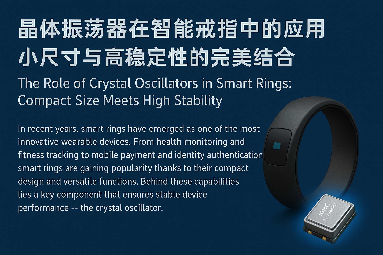
 

In recent years, smart rings have emerged as one of the most innovative wearable devices. From health monitoring and fitness tracking to mobile payment and identity authentication, smart rings are gaining popularity thanks to their compact design and versatile functions. Behind these capabilities lies a key component that ensures stable device performance — the crystal oscillator.

The Role of Crystal Oscillators in Smart Rings: Compact Size Meets High Stability

Crystal oscillators provide precise frequency and timing references for smart rings, making them essential for reliable operation. Their main applications include:

1.Stable Wireless Communication:

Smart rings typically connect to external devices via Bluetooth or NFC. High-precision crystal oscillators ensure stable communication frequencies, minimizing signal drift and improving connectivity.

2.Sensor Data Synchronization:

Sensors for heart rate, temperature, and motion require consistent sampling frequencies. Crystal oscillators deliver accurate clock signals, enabling precise data acquisition.

3.System Clock for MCUs:

The MCU or SoC inside the smart ring relies on a stable system clock. Crystal oscillators provide the core timing reference to ensure smooth and efficient system performance.

4.Low Power Consumption & Battery Life:

With limited battery capacity, smart rings benefit from low-power crystal oscillators such as 32.768 kHz RTC crystals, which enable precise timekeeping while extending standby duration.

5.Miniaturized Packaging:

Due to the compact design of smart rings, crystal oscillators are often integrated in ultra-small packages (e.g., 1.6×1.2 mm), balancing performance with space-saving requirements.As smart rings continue to evolve, the demand for crystal oscillators with smaller size, lower power, and higher stability will keep growing. JGHC Crystal will remain committed to delivering high-quality, customized frequency solutions, empowering innovation in the wearable technology market.

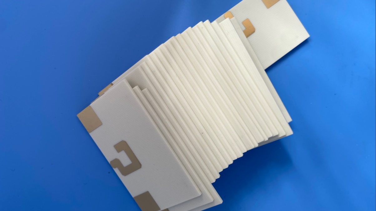
How Does Rogers TMM10 PCB Material Enhance Thermal and Electrical Performance?


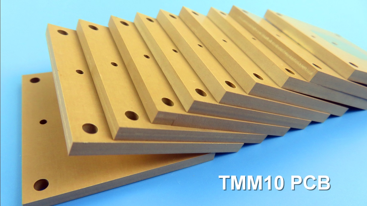
In the demanding world of high-frequency electronics, the choice of printed circuit board (PCB) substrate is paramount to the success of any application. Rogers Corporation's TMM10  microwave materials stand out as a superior solution, engineered to meet the rigorous requirements of modern RF and microwave circuits. This ceramic thermoset polymer composite is specifically designed for high plated-through-hole (PTH) reliability in both stripline and microstrip configurations, offering a unique blend of electrical and mechanical properties that bridge the gap between traditional materials.


Superior Material Properties for Enhanced Performance


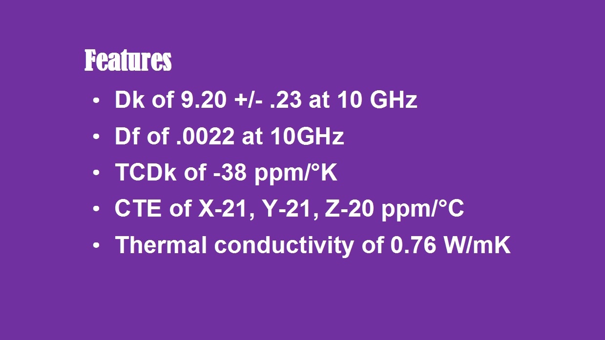
The TMM10 substrate is celebrated for its exceptional electrical characteristics, which directly contribute to more efficient and compact circuit designs. It boasts a stable dielectric constant (Dk) of 9.20 with a tight tolerance of±0.23. This high and consistent Dk is a significant advantage for designers aiming to minimize the physical size of components like antennas and filters, enabling substantial miniaturization without compromising performance.


TMM10's features


A critical factor in high-frequency applications is signal integrity, which is safeguarded by TMM10's remarkably low dissipation factor of 0.0022 at 10 GHz. This minimal loss tangent ensures that signal loss is drastically reduced, leading to enhanced efficiency and superior performance in power-sensitive applications. Furthermore, the thermal coefficient of dielectric constant (-38 ppm/°K) guarantees outstanding electrical stability across a wide range of operating temperatures, making it reliable in environments subject to thermal fluctuations.


TheTMM10 PCBmaterial’s mechanical and thermal properties are equally impressive. With a coefficient of thermal expansion (CTE) of 21 ppm/°K on the X and Y axes and 20 ppm/°K on the Z-axis, TMM10 closely matches the CTE of copper. This compatibility is crucial for producing highly reliable plated through-holes, preventing barrel cracking and ensuring long-term structural integrity. Additionally, its thermal conductivity of 0.76 W/m/K is approximately double that of standard PTFE/ceramic laminates, significantly improving heat dissipation and helping to manage thermal loads in power-amplifier and other heat-sensitive applications. The robust mechanical properties also effectively resist creep and cold flow, ensuring dimensional stability and durability under stress.


Advanced PCB Manufacturing Capabilities with TMM10

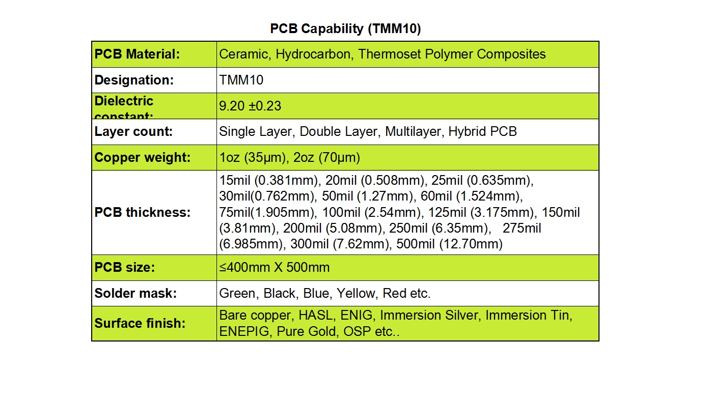
PCB Manufacturing Capabilities with TMM10


At Bicheng, we leverage our advanced manufacturing expertise to fully harness the potential of Rogers TMM10 laminates. We provide comprehensive PCB solutions tailored to diverse and complex project requirements. Our capabilities include the production of:


1)Layer Variations: Single-layer, double-layer, multilayer, and hybrid PCB constructions, offering design flexibility for various circuit complexities.


2)Copper Weights: Standard options of 1oz (35µm) and 2oz (70µm) to cater to different current-carrying and thermal management needs.


3)Board Thickness: A wide range from a slender 15mil (0.381mm) to a substantial 500mil (12.70mm), supporting everything from ultra-compact to extremely robust and durable designs.


4)Panel Size: Capable of handling large formats up to 400mm x 500mm, ideal for sizable projects and efficient panelization.


5)Aesthetics and Finish: A selection of solder mask colors (green, black, blue, yellow, red) and a variety of surface finishes including Bare Copper, HASL, ENIG, Immersion Silver, Immersion Tin, ENEPIG, Pure Gold, and OSP to meet both technical and aesthetic specifications.


Rogers TMM10 PCB


Diverse Application Spectrum

The exceptional properties of TMM10 PCBs make them the material of choice for a wide array of high-performance applications. They are commonly deployed in:


1)Chip Testers: Where signal integrity and thermal stability are critical for accurate testing.


2)Dielectric Polarizers and Patch Antennas: Benefiting from the stable high Dk for compact, efficient design.


3)Satellite Communication Systems and GPS Antennas: Where low signal loss and reliability under varying environmental conditions are non-negotiable.


Conclusion

Rogers TMM10 represents a paradigm shift in high-frequency PCB materials, combining the best attributes of ceramics and polymers without their inherent limitations. For engineers designing next-generation RF and microwave products, TMM10 offers a path to miniaturization, enhanced reliability, and superior electrical performance. As a trusted PCB supplier, Bicheng possesses the technical proficiency to transform this advanced material into high-quality, reliable circuit boards that meet your most challenging application demands.


Contact us today to discuss how we can support your specific project needs with our TMM10 high frequency PCB capabilities.

What Should You Know About Manufacturing PCBs with Rogers DiClad 880 Material?


In the demanding world of high-frequency electronics, the choice of printed circuit board (PCB) substrate is a critical determinant of performance, reliability, and signal integrity. For engineers and designers working on cutting-edge RF and microwave applications, Rogers Corporation’s DiClad 880 high frequency laminate stands out as a superior PTFE-based composite solution. This blog delves into the unique properties, manufacturing capabilities, and diverse applications of DiClad 880, illustrating why it is an ideal material for your most challenging projects.


An Overview of DiClad 880 High Frequency Laminates

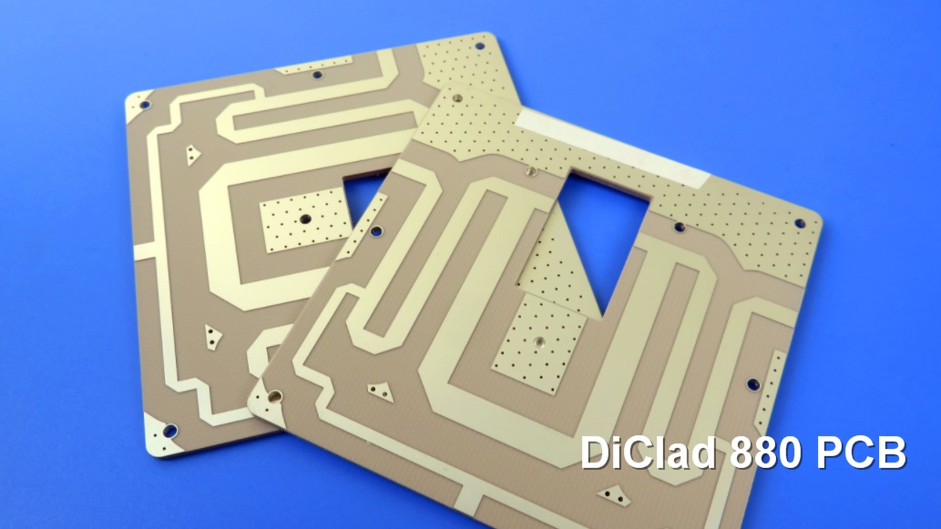
Rogers DiClad 880 PCB is engineered as a polytetrafluoroethylene (PTFE) composite system reinforced with woven fiberglass. What distinguishes it from other laminates is its strategic material composition: by incorporating fewer plies of glass weave and a higher proportion of PTFE, DiClad 880 PCB achieves a reduced dielectric profile even at comparable thickness levels. This design yields two major electrical benefits—a consistently low dielectric constant (Dk) and exceptionally minimal signal loss, making it especially suitable for high-precision, high-speed circuits.


Typical applications include filters, couplers, and low-noise amplifiers where uniform Dk is essential. Moreover, its low-loss characteristics make it highly desirable in power dividers and combiners, among other RF components.


Key Features and Performance Advantages

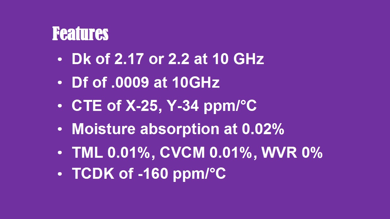
One of the most defining attributes of DiClad 880 is its stable dielectric constant, available at either 2.17 or 2.20. This low Dk is paired with an ultra-low dissipation factor (loss tangent) of just 0.0009 at 10 GHz—a remarkable achievement for a PTFE-glass hybrid laminate, ensuring high signal fidelity and minimal energy waste in operation.


Diclad 880 PCB Features


Beyond electrical performance, DiClad 880 offers outstanding mechanical stability. The woven fiberglass reinforcement significantly improves dimensional stability, outperforming non-woven alternatives with similar Dk values. Its thermal expansion characteristics are well controlled, with a Coefficient of Thermal Expansion (CTE) of 25 ppm/°C in the X-axis and 34 ppm/°C in the Y-axis.


The material also excels in environmental resilience. It absorbs only 0.02% moisture, safeguarding electrical properties in humid conditions, and complies with the UL 94-V0 flammability rating, enhancing end-product safety. Furthermore, DiClad 880 demonstrates exceptional outgassing performance, with a Total Mass Loss of 0.01% and Collected Volatiles of 0.01%, with no water vapor recovery—making it a reliable candidate for aerospace and other high-reliability fields.


It is important, however, to consider certain limitations during the design phase. DiClad 880 has a thermal conductivity of 0.25 W/m/K and a thermal coefficient of dielectric constant (TCDk) of -160 ppm/°C. These values necessitate thoughtful thermal management strategies in high-power or wide-temperature-range applications.


PCB Manufacturing Capabilities with DiClad 880

Our manufacturing facilities are fully equipped to produce high-performance PCBs using DiClad 880 laminates, catering to both prototype and volume production needs.


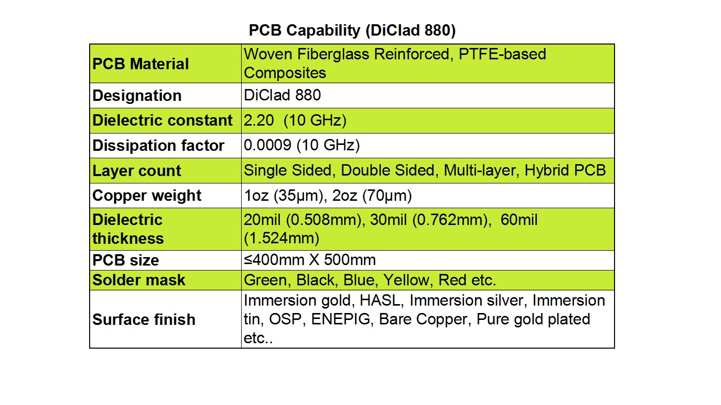
PCB Manufacturing Capabilities with DiClad 880


1)Layer Count: We support single-sided, double-sided, multilayer, and hybrid PCB structures.


2)Copper Weights: Standard options include 1 oz (35 µm) and 2 oz (70 µm) to balance current carrying capacity and fine-line etching requirements.


3)Dielectric Thickness: Available in 20 mil (0.508 mm), 30 mil (0.762 mm), and 60 mil (1.524 mm) to meet impedance control and mechanical design specs.


4)Board Dimensions: We can process panels up to 400 mm x 500 mm.


5)Solder Mask: Multiple color options are offered including green, black, blue, yellow, and red for both identification and aesthetic purposes.


6)Surface Finishes: A broad selection is available such as ENIG (Immersion Gold), HASL, Immersion Silver, Immersion Tin, OSP, ENEPIG, bare copper, and gold plating—each providing distinct advantages for solderability, durability, and performance.


  DiClad 880 High Frequency PCBs


Applications of DiClad 880 High Frequency PCBs

Thanks to its outstanding high-frequency characteristics,Rogers DiClad 880 is widely employed across industries where signal loss and stability are non-negotiable. In addition to the uses mentioned earlier, it is often specified in military radar feed networks, commercial phased array antenna systems, low-loss base station antennas, and digital radio antennas. Its blend of electrical excellence and mechanical robustness makes it a future-proof selection for next-generation communication and sensing technologies.


Conclusion

Rogers DiClad 880 high frequency PCBs provide an optimal combination of low dielectric loss, stable mechanical properties, and excellent reliability—enabling advanced electronic systems to perform with precision. Whether you are developing RF communication modules, aerospace radar, or advanced antenna systems, DiClad 800 delivers the performance and quality your application demands.


As an experienced PCB supplier, we offer end-to-end manufacturing support for DiClad 880-based circuits, ensuring that your designs are realized with the highest standards of accuracy and repeatability.


Why is RF-35 a Top-Tier, Cost-Effective Material for Commercial Microwave and RF Designs?


In the rapidly advancing world of wireless technology, the selection of the right printed circuit board material is paramount to the success of any high-frequency application. For engineers and designers seeking an optimal blend of performance, reliability, and cost-efficiency, Taconic's RF-35 High Frequency PCB laminate emerges as a premier solution. This blog post delves into the superior properties, extensive manufacturing capabilities, and diverse applications of RF-35, underscoring why it is a standout material for your next project.


An Introduction to RF-35 High Frequency PCB Laminate

Taconic RF-35 is a high-performance, organic-ceramic laminate belonging to Taconic's esteemed ORCER series. This material is engineered with a woven glass reinforcement system, synergizing the company's profound expertise in advanced ceramic filler technology with a specialized coated PTFE (Polytetrafluoroethylene) fiberglass substrate. A key differentiator of RF-35 is its utilization of 7628-style fiberglass, which provides an exceptional balance of mechanical stability and electrical performance, offering outstanding value. It is notably available in consistent thickness increments of 10 mils (0.254 mm), facilitating straightforward design and integration.


This Taconic RF-35 substrate is specifically engineered to serve as an ideal substrate for cost-sensitive, high-volume commercial microwave and radio frequency (RF) products. It boasts excellent peel strength, significantly surpassing standard epoxy-based materials. This is critical for both half-ounce and 1-ounce copper weights, ensuring robust connections that can withstand rework and repair processes without failure. Furthermore, RF-35 exhibits an ultra-low moisture absorption rate and a remarkably low dissipation factor (Df). These characteristics are vital for maintaining stable electrical performance, as they effectively minimize undesirable phase shift and signal loss across a broad frequency spectrum.


Detailed Analysis of Key Parameters

The exceptional performance of RF-35 is quantitatively validated through rigorous testing per IPC and ASTM standards, providing designers with reliable data for their simulations and calculations.


rf-35 pcb features


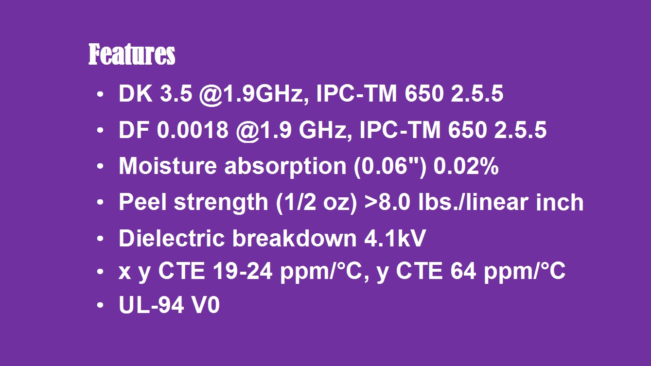
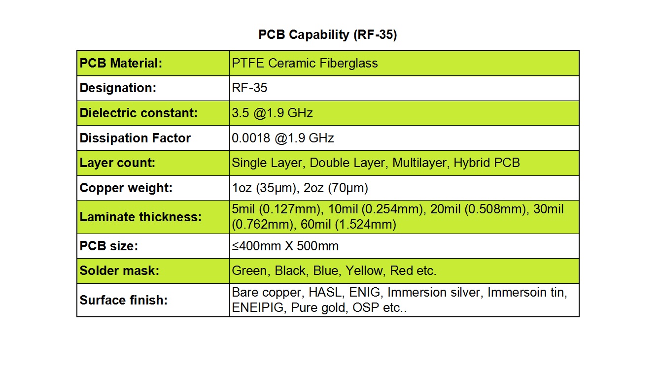
1)Dielectric Properties: At a test frequency of 1.9 GHz (IPC-TM 650 2.5.5), RF-35 demonstrates a stable dielectric constant (Dk) of 3.50 and an extremely low dissipation factor of 0.0018. This combination of low Dk and minimal signal loss is precisely what makes it ideal for high-frequency circuits where preserving signal integrity is absolutely crucial.


2)Moisture Resistance: As per IPC-TM 650 2.6.2.1 testing on a 0.060-inch thick sample, the material's moisture absorption is a mere 0.02%. This extremely low value ensures that the board's electrical properties remain consistent even in varying environmental conditions, preventing performance degradation due to humidity.


3)Mechanical Strength: The peel strength, a direct measure of the bond between the copper and the laminate, is exceptional. For½oz. copper, it exceeds 8.0 lbs/linear inch, and for 1 oz. copper, it surpasses 10.0 lbs/linear inch (IPC-TM 650 2.4.8). This high strength prevents delamination and ensures reliability.


4)Electrical and Thermal Reliability: The dielectric breakdown strength, tested per IPC-TM 650 2.5.6, is rated at 41 kV, indicating high voltage resistance. Its coefficient of thermal expansion (CTE) is measured by ASTM D 3386 (TMA), with x/y CTE values of 19 and 24 ppm/°C and a z-axis CTE of 64 ppm/°C, providing good dimensional stability during thermal cycling. Finally, it carries a flammability rating of UL-94 V-0, meeting critical safety standards.


PCB Manufacturing Capabilities with RF-35

We offer comprehensive and versatile fabrication services tailored to fully leverage the advantages of RF-35 PCB laminate, accommodating a wide array of project specifications.


PCB Manufacturing Capabilities with RF-35


1)Board Construction: We can manufacture single-layer, double-layer, complex multilayer, and hybrid multilayer PCBs, providing design flexibility for various application complexities.


2)Copper and Laminate Thickness: Standard copper weights include 1oz (35µm) and 2oz (70µm). We provide a selection of laminate thicknesses including 5 mil (0.127 mm), 10 mil (0.254 mm), 20 mil (0.508 mm), 30 mil (0.762 mm), and 60 mil (1.524 mm).


3)Panel Size: We support PCB sizes up to 400 mm x 500 mm, offered either as individual boards or as multi-size arrays within a single panel, maximizing production efficiency.


4)Aesthetics and Finish: A variety of solder mask colors are available, including green, black, blue, yellow, and red. We also provide a comprehensive range of surface finishes such as Bare Copper, HASL, ENIG, Immersion Silver, Immersion Tin, ENEPIG, Pure Gold, and OSP to meet specific assembly and performance needs.


RF-35 high frequency PCB


Primary Applications

The superior electrical and mechanical properties of RF-35 high frequency PCB make it exceptionally well-suited for a multitude of critical RF components. It demonstrates strong performance in power amplifiers, filters, couplers, and a wide array of other passive components essential for modern communication systems, satellite technology, and radar applications.


Conclusion

For OEMs and designers navigating the challenges of high-frequency electronics, RF-35 PCB represents a proven, high-value material solution. Its certified electrical parameters, outstanding reliability, and our extensive manufacturing support make it a top contender for your most demanding commercial RF and microwave projects. Contact us today to discuss how we can partner to bring your innovative designs to life with RF-35 High Frequency PCBs.

Why is TC600 High Frequency PCB Ideal for Demanding RF and Microwave Applications?


In the rapidly advancing world of electronics, the demand for high-frequency printed circuit boards (PCBs) that offer exceptional reliability and performance is higher than ever. For engineers and designers working on cutting-edge RF and microwave applications, the choice of substrate material is a critical decision that directly impacts the success of a project. Rogers Corporation’s TC600 high-frequency laminate emerges as a superior solution, specifically engineered to meet the rigorous demands of modern wireless technology. This PTFE-based composite material, reinforced with woven fiberglass and optimized with ceramic fillers, establishes a new benchmark for high-frequency PCB substrates, delivering a combination of electrical and thermal performance that is truly best-in-class.


Introduction

Rogers TC600 is a high-performance polytetrafluoroethylene (PTFE) composite material engineered for advanced printed circuit boards. It incorporates woven fiberglass and specialized ceramic fillers, delivering exceptional thermal and electrical properties. Recognized for its best-in-class thermal conductivity, this substrate significantly reduces dielectric and insertion losses—making it ideal for high-frequency applications such as amplifiers and antennas.


The Rogers TC600 PCB material’s superior thermal management capabilities support higher power densities, reduce the risk of localized overheating, and enhance overall device longevity. Its efficient heat dissipation works seamlessly with thermal management techniques like embedded coins, heat sinks, and thermal vias, offering designers greater flexibility and reliability in thermal planning.


Features

TC600 laminates provide a combination of electrical and mechanical properties tailored for demanding RF and microwave applications:


Features TC600 laminate 


1)High Dielectric Constant (Dk): 

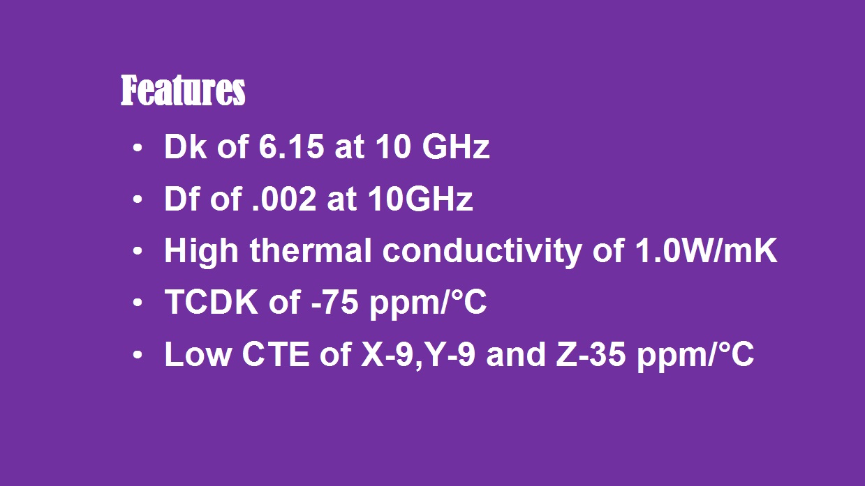
With a Dk of 6.15, the material supports circuit miniaturization, enabling more compact and efficient designs.


2)Low Dissipation Factor:

At 10 GHz, the dissipation factor is as low as 0.002, ensuring minimal signal attenuation and improved performance in high-frequency circuits.


3)Anisotropic Thermal Conductivity:

The Z-axis thermal conductivity reaches 1.1 W/m·K, while the X and Y axes offer 1.4 W/m·K. This directional efficiency promotes effective heat spread and dissipation.


4)Temperature Stability:

The dielectric constant remains consistent across a broad temperature spectrum (-40°C to 150°C) thanks to a TCDk of -75 ppm/°C. This stability is essential for power amplifiers and antennas to maintain gain and bandwidth under varying operational conditions.


5)Controlled Thermal Expansion:

A Z-direction CTE of 35 ppm/°C ensures mechanical reliability of plated through-holes, reducing the risk of failure in thermal cycling.


PCB Manufacturing Capabilities

We provide end-to-end PCB fabrication services tailored to high-frequency designs using Rogers TC600 material:


TC600 PCB Manufacturing Capabilities


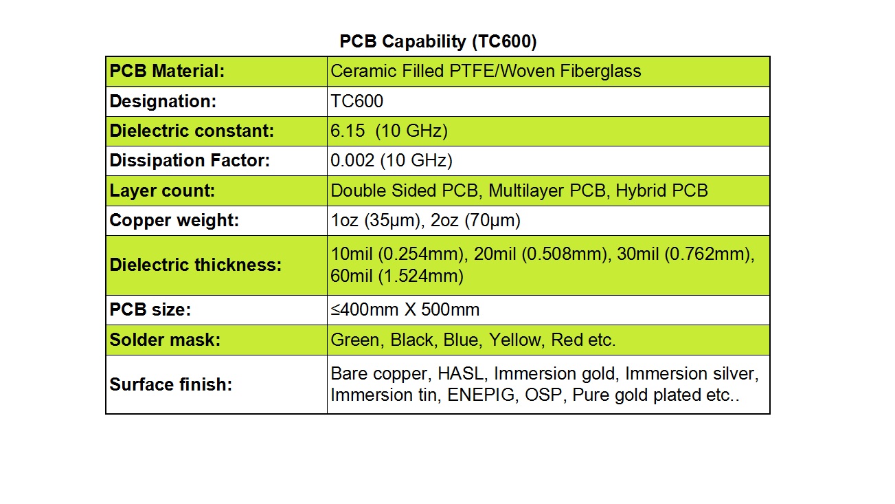
1)Layer Construction: We produce double-sided, multilayer, and hybrid PCBs to meet diverse design requirements.


2)Copper Options: Standard copper weights include 1 oz (35 µm) and 2 oz (70 µm), with customization available for specific current-carrying or thermal needs.


3)Dielectric Thickness: Available in 10 mil (0.254 mm), 20 mil (0.508 mm), 30 mil (0.762 mm), and 60 mil (1.524 mm) to support impedance control and signal integrity.


4)Board Dimensions: We accommodate panels up to 400 mm x 500 mm, suitable for both prototyping and volume production.


5)Solder Mask Colors: Options include green, black, blue, yellow, red, and others for aesthetic and functional preferences.


6)Surface Finishes: Choose from Bare Copper, HASL, ENIG, Immersion Silver, Immersion Tin, ENEPIG, OSP, and Pure Gold Plating to optimize solderability and surface durability.


TC600 high-frequency PCBs


Applications

TC600 high-frequency PCBs are widely used in RF and microwave systems, including:


  • Power amplifiers, filters, and directional couplers
  • Avionics systems such as microwave combiners and power dividers
  • Compact and high-gain antennas
  • Digital audio broadcasting (DAB) and satellite radio antennas
  • GPS and handheld RFID reader antennas


In conclusion, Rogers TC600 High Frequency PCBs represent a powerful synergy of material science and manufacturing expertise. By offering unmatched thermal management, minimal signal loss, and exceptional reliability, they provide a critical advantage for the most demanding RF and microwave designs.


Why Should You Choose RO4835 Laminates for Your Next RF or Microwave PCB Project?


In the world of high-frequency printed circuit boards (PCBs), material selection plays a critical role in determining the overall performance, reliability, and longevity of the final product. Traditional thermoset laminate materials, such as FR-4, are prone to oxidation—especially under elevated temperatures. This oxidation can lead to undesirable increases in the dielectric constant (Dk) and dissipation factor (Df), ultimately compromising signal integrity and circuit performance.


Rogers Corporation’s RO4835 high-frequency laminate is specifically engineered to overcome these limitations. With superior resistance to oxidation and exceptional stability under thermal stress, Rogers RO4835 offers an ideal substrate solution for high-frequency and RF applications. What’s more, it delivers electrical and mechanical properties comparable to those of the widely used RO4350B laminates, but with enhanced cost-efficiency and compatibility with standard FR-4 manufacturing processes.


Key Features of RO4835 High Frequency Laminates

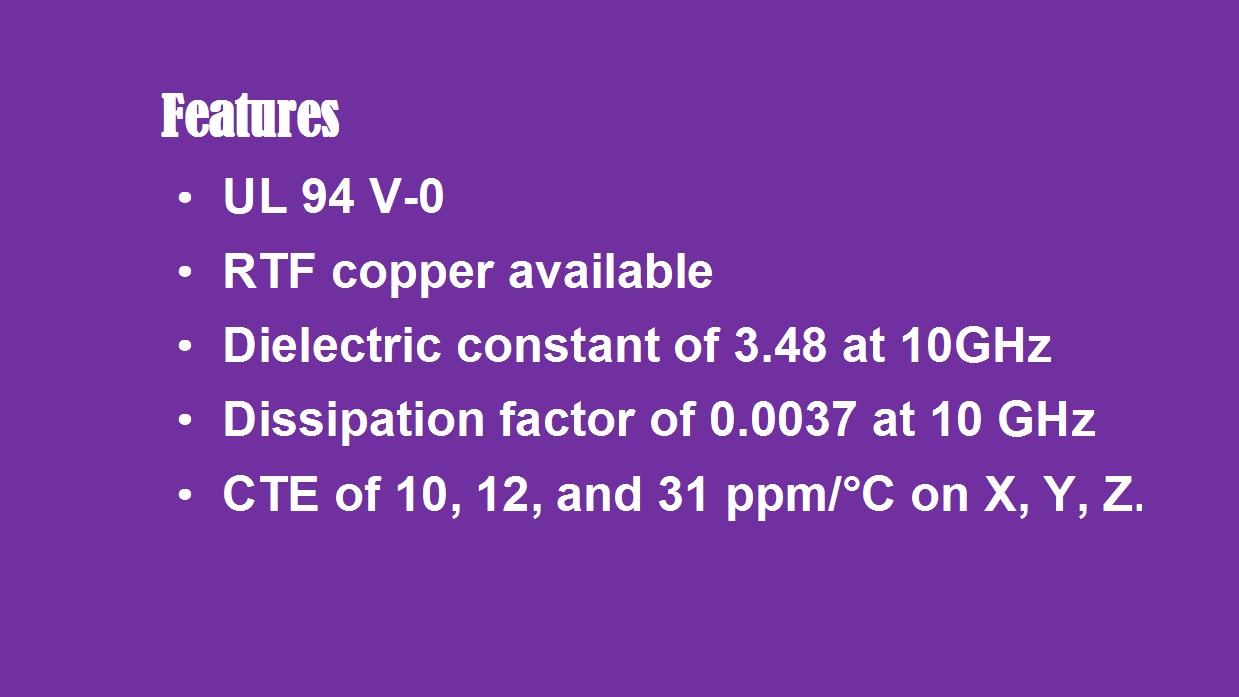
One of the standout attributes of Rogers 4835 PCB is its compliance with RoHS and UL 94 V-0 standards, making it both environmentally friendly and flame-retardant. This makes it suitable for use in demanding industries where safety and regulatory compliance are non-negotiable.


Key Features of RO4835 High Frequency Laminates


Another significant advantage is the availability of Rogers' proprietary LoPro™Reverse treated copper foil. This specialized foil treatment minimizes insertion loss, making RO4835 PCB an excellent choice for applications where signal integrity and low loss are paramount.


Electrical consistency is another area where RO4835 excels. It boasts a stable dielectric constant of 3.48 with very tight tolerances, ensuring predictable performance across various frequencies—a crucial factor in RF and microwave circuit design. Additionally, its dissipation factor is as low as 0.0037 at 10 GHz, meaning minimal signal loss even in high-frequency scenarios.


From a mechanical standpoint, RO4835 exhibits outstanding dimensional stability due to its low coefficient of thermal expansion (CTE). With CTE values of 10 ppm/°C in the X direction, 12 ppm/°C in the Y direction, and 31 ppm/°C in the Z direction, this material significantly reduces the risk of delamination or plated-through-hole failure under thermal cycling.


PCB Manufacturing Capabilities with RO4835

We support a wide range of PCB configurations using RO4835 substrates, including single-sided, double-sided, multi-layer, and hybrid constructions. This allows for design flexibility whether you are working on a simple RF switch or a complex phased-array radar system.


PCB Manufacturing Capabilities with RO4835


To accommodate diverse electrical requirements, we offer standard copper weights of 1oz (35µm) and 2oz (70µm). Dielectric thickness is also highly adaptable: for ED copper, thickness ranges from 6.6 mil (0.168 mm) to 60 mil (1.524 mm); for LoPro copper, it ranges from 4 mil (0.102 mm) to 60.7 mil (1.542 mm).


We can produce PCBs with maximum dimensions of 400mm x 500mm, suitable for both prototyping and volume production. A variety of solder mask colors—including green, black, blue, yellow, and red—are available to meet aesthetic or branding preferences.


Surface finish options are equally comprehensive, featuring bare copper, HASL (Hot Air Solder Leveling), immersion gold (ENIG), immersion silver, immersion tin, OSP (Organic Solderability Preservative), and pure gold plating. This ensures compatibility with virtually any assembly process and end-use environment.


RO4835 high-frequency PCBs


Typical Applications

RO4835 high-frequency PCBs are ideally suited for a variety of advanced electronic applications, including:


  • Automotive radar and sensor systems
  • Point-to-point microwave communication links
  • High-power amplifiers
  • Phased-array radar systems
  • General RF components and subsystems


Whether you are developing cutting-edge automotive safety systems, communication infrastructure, or defense electronics, RO4835 provides a reliable, high-performance foundation for your most demanding circuits.


In today’s fast-paced world, a smartwatch is more than just a timepiece—it’s a personal assistant, fitness companion, and style statement all in one. The North Edge HT30 redefines what a smartwatch can be, combining cutting-edge technology with premium craftsmanship. The large HD round display delivers a stunning visual experience, making notifications, fitness data, and apps easy to read at a glance. Housed in a lightweight yet durable titanium alloy case, the HT30 offers both elegance and resilience, suitable for every lifestyle.


Performance is at the heart of the HT30. Equipped with a 600mAh battery and a precision motion algorithm, it ensures uninterrupted tracking of health and fitness activities. The watch supports over 100 professional sports modes and features a built-in health monitoring chip, allowing you to track heart rate, sleep, and other vital stats with ease.


For outdoor enthusiasts, the HT30 is a game-changer. With IP68 waterproofing, a compass, floodlight, SOS, and purple light identification lamp, you can explore confidently day or night, whether hiking, sailing, or swimming. Customization is another highlight, as users can choose from a variety of dial themes and strap colors, ensuring the watch matches personal style and occasions.


Whether you’re seeking adventure, fitness tracking, or simply a smart companion that keeps you connected, the North Edge HT30 delivers. With its powerful features and premium design, it’s more than a smartwatch—it’s a lifestyle upgrade.


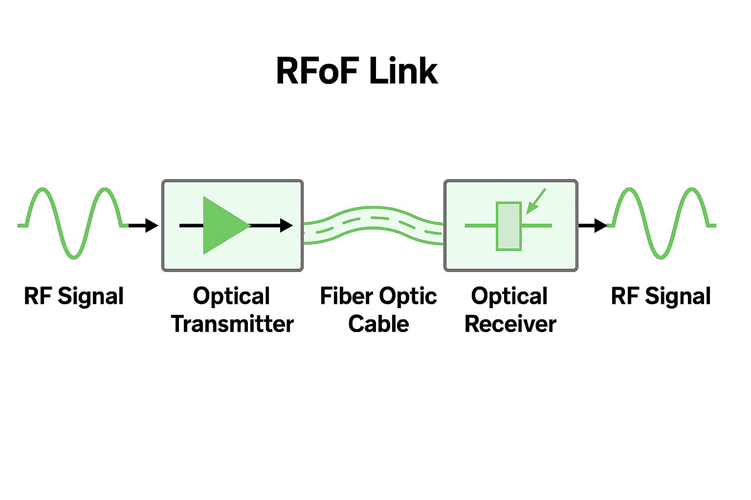
In many communication systems, RF signals need to travel tens of kilometers. At lower frequencies coaxial cables are still usable, but once you move into the multi-GHz range, loss and interference quickly become unacceptable.


RFoF (Radio over Fiber) addresses this by directly modulating RF signals onto an optical carrier, sending them through fiber, and recovering them at the remote end. This combines the low loss and wide bandwidth of optical fiber with the simplicity of bypassing additional frequency conversions.

RFoF Technology

Frequency Range and Link Characteristics

A typical 6 GHz RFoF module covers 5 MHz – 6000 MHz. End-to-end link gain is about 22 dB, with flatness within ±2.5 dB across the full band. Over a narrower 36 MHz span, flatness can be as good as ±0.25 dB. This matters for multi-carrier or broadband signals, since flatter response reduces equalization overhead.


Dynamic Range and Noise

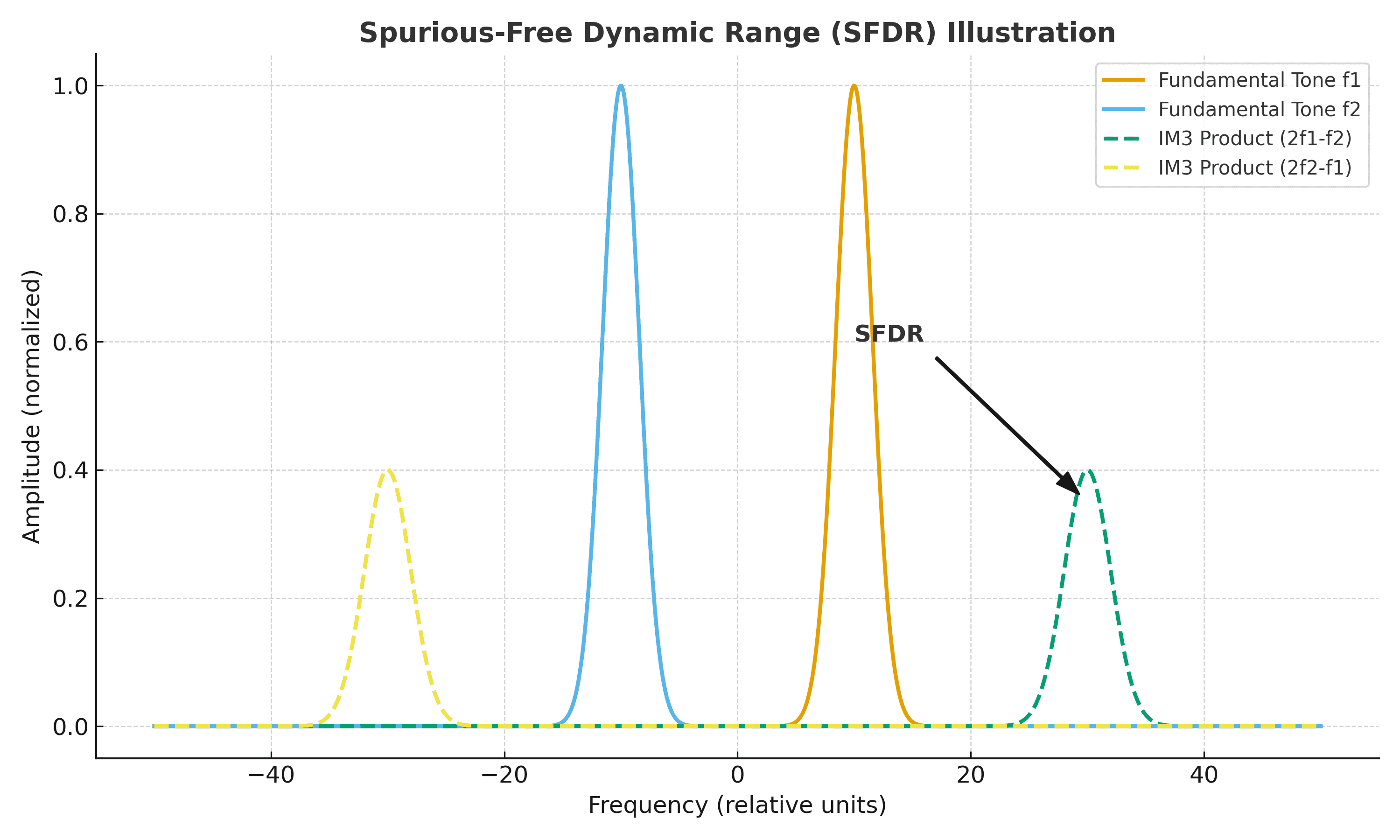
Two key metrics for any RFoF link are the noise figure (NF) and the spurious-free dynamic range (SFDR).

  • NF is around 16 dB, which allows weak signals to remain usable after transport.
  • SFDR is about 104 dB·Hz^(2/3), indicating how well the link can handle strong and weak signals together without distortion.

For example, in a 10 MHz bandwidth, this translates to an effective dynamic range on the order of 70–80 dB—sufficient for most fronthaul and satellite reception scenarios.

RFoF's Spurious-Free Dynamic Range (SFDR) Illustration

Environmental and Interface Considerations

These modules typically operate from –20 °C to +75 °C, with storage limits from –40 °C to +85 °C. Common interfaces include FC/APC optical connectors, with selectable wavelengths at 1310 nm or 1550 nm. Power is usually 5 V at ~150 mA, keeping power consumption low and integration straightforward.


Application Scenarios

  • 5G / LTE fronthaul: linking base stations and remote RF units with low latency and high bandwidth;
  • Satellite ground stations: carrying high-frequency signals from antenna sites to control rooms;
  • CATV / HFC networks: replacing coax over long spans to reduce attenuation;
  • Research facilities: radio telescopes and other low-noise signal transport needs.


Conclusion

RFoF is not a universal solution, but when frequencies extend into the GHz range and distances span kilometers, it offers clear advantages: wide bandwidth, low loss, and strong dynamic range. Understanding link budget and parameter trade-offs is key to building reliable systems.


Full specifications can be found in the technical datasheet.


LED digital tube, TFT lcd screen, and OLED screen are three types of screens widely used in electronic devices, with significant differences in composition, technical principles, and applications.

1、 LED digital tube

Composition: The LED digital tube is composed of multiple LED light-emitting diodes, each corresponding to a part of a number or symbol on the digital tube. They are encapsulated in a transparent plastic or glass casing to form a cohesive display unit.

Technical principle: The working principle of LED digital tube is based on the luminous characteristics of LED. When current passes through an LED, the LED emits light, and the color of the light depends on the material of the LED. In a digital display, numbers, letters, or symbols can be displayed by controlling the brightness of different LEDs.

Application: LED digital tubes are widely used in various occasions that require digital display, such as electronic clocks, counters, thermometers, etc., due to their simple structure, low price, and easy control.

Advantages: Energy saving and environmental protection: LED digital tubes have higher energy saving and environmental protection characteristics compared to traditional LCD displays. Due to its use of DC drive, it has lower power consumption and does not require the use of LCD screens, making it more energy-efficient. Lower cost: Compared to some high-end display technologies, LED digital tubes have a relatively lower price and are more suitable for use in some mid to low end application scenarios. Strong customizability: LED digital tubes can display different characters through different combinations of LEDs, thus having high customizability and allowing for different designs and production according to needs.

Disadvantages: Limited display effect: Compared with TFT and OLED screens, LED digital tubes have a simpler display effect and are usually used to display numbers, letters, and simple graphics. They are not suitable for displaying high-definition videos or complex images.

2、 TFT lcd screen (Thin Film Transistor)

Composition: TFT lcd screen is composed of multiple complex components, including liquid crystal layer, backlight module, thin film transistor, color filter, polarizer, etc. The liquid crystal layer is the core part of TFT screen, used to control the transmission and obstruction of light; The backlight module provides a light source; Thin film transistors act as switching elements to control the brightness of each pixel.

Technical principle: TFT screen belongs to a type of active matrix liquid crystal display. It controls the alignment direction of liquid crystal molecules through thin film transistors, thereby controlling the amount of light transmitted. When current passes through a thin film transistor, an electric field is generated to deflect liquid crystal molecules, thereby changing the transmittance of light and achieving image display.

Application: TFT screens are widely used in high-end electronic products such as smartphones, tablets, LCD TVs, etc. due to their advantages of high definition, high color reproduction, and low energy consumption.

Advantages: High Resolution: TFT screens typically have high resolution and can present clear images and text, making them suitable for tasks such as reading, watching high-definition videos, and graphic design. Fast response time: Due to the use of LCD technology, TFT screens have a fast response time, suitable for playing dynamic content and games, reducing motion blur and ghosting. Multifunctionality: TFT screens are widely used in various electronic devices, including smartphones, tablets, televisions, computer monitors, etc., to meet different user needs. Wide viewing angle: TFT screens typically have a good viewing angle and can maintain image quality even at oblique angles.

Disadvantages: High energy consumption: TFT screens typically require a backlight source to generate brightness, which may result in higher energy consumption, especially when displaying high brightness content. Black level limitation: Compared to OLED, TFT screens may have some limitations when displaying dark black, as LCD cannot completely turn off the light source.

3、 OLED screen (Organic Light Emitting Diode)

Composition: OLED screen is composed of organic light-emitting material layer, anode, cathode, and encapsulation layer. The organic light-emitting material layer is the core part of OLED screens, and when current passes through it, the organic material emits light.

Technical principle: The working principle of OLED screens is based on the electroluminescence phenomenon of organic materials. When current passes through the organic luminescent material layer, electrons and holes recombine in the luminescent layer to produce excitons, which release energy and emit light when they decay. Each pixel of an OLED screen can independently emit light and control brightness, thus having extremely high contrast and color saturation.

Application: OLED screens are widely used in fields such as smartphones, high-end TVs, wearable devices, etc. due to their advantages of self illumination, high contrast, wide viewing angle, and low power consumption. In addition, OLED screens can also achieve curved and flexible design, providing more possibilities for product design.

Advantages: Self luminous: OLED screens emit light at each pixel, making them thinner and lighter than LCDs, and do not require a backlight source, allowing for higher contrast and deeper black color. Low power consumption: OLED screens save structures such as backlight, LCD, and color filters, resulting in lower power consumption. Flexible display: OLED screens can achieve flexible display, providing more possibilities for future electronic device design. Vibrant colors: OLED screens have higher color saturation, resulting in more vivid image colors.

Disadvantages: High cost: The production process of OLED screens is complex, so the price is relatively high. Short lifespan: OLED organic materials have a limited lifespan, typically only a few thousand hours. Risk of burn-in: OLED screens may experience burn-in when displaying static images for a long time at low brightness. We are professional lcd display manufacturer, get more details from www.gvlcd.com quickly.