According to the latest report released by the globally renowned market research firm Omdia, the global shipment of LCD panels (9 inches and above) is expected to reach 875 million units by 2025, a year-on-year increase of 2.9%, and the market is showing a steady recovery trend. Among them, panel manufacturers in Chinese Mainland have performed particularly well. It is estimated that the shipment volume will increase by 4.8%, and continue to lead the global market.


According to the analysis of the report, this growth is mainly due to the strong cost control ability of manufacturers in Chinese Mainland, complete industrial chain support and flexible market strategy. Faced with market fluctuations, major manufacturers have adopted a strategy of "conservative expansion" and "on-demand production", effectively maintaining the supply and demand balance and price stability of the global LCD market, and avoiding vicious competition. In addition, the demand for segmented markets such as in car displays, high-end commercial displays, and smart home control screens has provided new impetus for the growth of the LCD industry.


As an important participant in the LCD industry, Golden Vision closely monitors global market trends and actively optimizes its production capacity layout and product structure. The company is committed to providing customers with high-performance and high reliability industrial and commercial grade LCD displays, and has won a good reputation in the global market with fast response and customized services.


The Marketing Director of Golden Vision stated, 'We agree with Omdia's assessment of market trends.'. The future competition will be a comprehensive competition of technology, quality, and supply chain stability. Golden Vision will continue to focus on technological innovation, deepen its layout in sub sectors such as industrial control and healthcare, and grow together with customers.


gvlcd


In the rapidly evolving world of display technology, two names stand out: TFT LCD and OLED. As a leading provider of innovative display solutions, Goldenvision is often asked: which display technology is superior? The answer isn't straightforward, as each has its own strengths and ideal use cases. In this article, we’ll break down the differences to help you make an informed decision.


What is TFT LCD?

TFT LCD (Thin-Film Transistor Liquid Crystal Display) is a variant of LCD that uses thin-film transistor technology to improve image quality. Each pixel is controlled by one to four transistors, allowing for sharper and more vibrant images compared to traditional LCDs.

Advantages of TFT LCD:

High Brightness: Ideal for outdoor use and well-lit environments.

Long Lifespan: Less susceptible to screen burn-in compared to OLED.

Cost-Effective: Generally more affordable for larger displays.

Wide Availability: Commonly used in smartphones, monitors, and televisions.


Key Comparisons

Feature

TFT LCD

OLED

Black Levels

Good

Excellent

Brightness

High

Moderate

Response Time

Slower

Faster

Lifespan

Longer

Shorter

Cost

Lower

Higher

Flexibility

Rigid

Flexible


What is OLED?

OLED (Organic Light-Emitting Diode) technology uses organic compounds that emit light when an electric current is applied. Unlike TFT LCDs, OLED displays do not require a backlight, allowing for deeper blacks and more vibrant colors.

Advantages of OLED:

Perfect Blacks: Individual pixels can turn off completely, resulting in infinite contrast ratios.

Faster Response Times: Better for fast-moving content like gaming and sports.

Flexibility: Can be used in curved or flexible displays.

Energy Efficiency: Consumes less power when displaying dark content.


Which One Should You Choose?

Choose TFT LCD If:

You need a display for bright environments.

You prioritize longevity and reduced risk of burn-in.

Budget constraints are a concern.


Choose OLED If:

You want superior image quality with deep blacks and vibrant colors.

You need a display for multimedia consumption or gaming.

Flexibility and sleek design are important.


Conclusion

Both TFT LCD and OLED have their unique advantages. At Goldenvision, we offer a range of display solutions tailored to your needs. Whether you value the reliability and brightness of TFT LCD or the stunning visuals of OLED, we have the perfect display for you.

Contact us today to learn more about our products and find the ideal display technology for your application!

Look around you. Whether you're reading this on your smartphone, glancing at your laptop monitor, or checking the time on your smartwatch, there's a very high chance you're looking at a TFT LCD display. This technology is the workhorse behind the visual interface of countless modern devices. But what exactly is a TFT LCD, and how does it create the bright, colorful images we see every day? Let's dive in and demystify this engineering marvel.


tft lcd display


What is a TFT LCD?


First, let's break down the acronym:


LCD (Liquid Crystal Display): An LCD is a flat-panel display that uses the light-modulating properties of liquid crystals. These crystals don't produce their own light; instead, they rely on a backlight and act like tiny shutters to either block or allow light to pass through.


TFT (Thin-Film Transistor): This is the active matrix technology that drives the LCD. A TFT is a special type of transistor made from a thin film of semiconductor material deposited on a glass panel. For every single pixel on the screen, there are one or more of these tiny transistors.


So, a TFT LCD is essentially an active matrix LCD where each pixel is controlled by one to four transistors. This setup allows for faster response times, sharper images, higher contrast, and better color reproduction compared to older, passive matrix LCDs. It's the "smart" and precise way to control an LCD.


How Does a TFT LCD Work?


The magic of a TFT LCD lies in its layered structure and precise control of light. Here’s a step-by-step breakdown:


1. The Backlight:

The process starts with a bright white LED backlight at the rear of the display assembly. This light source is always on, providing the illumination for the entire screen.


2. The Polarizers:

The light first passes through a polarizing filter. This filter only allows light waves vibrating in a specific direction to pass through, creating polarized light.


3. The Liquid Crystal Layer:

This polarized light then reaches the layer of liquid crystals. Each pixel is made up of three sub-pixels—red, green, and blue (RGB)—each with its own transistor. By applying a precise electrical voltage via the TFT, the twist of the liquid crystals changes. This twisting action either twists the polarized light to allow it through or untwists to block it, acting like a microscopic shutter for each sub-pixel.


4. The Color Filter:

After passing through the liquid crystal layer, the light hits a color filter. This filter has individual red, green, and blue segments for each sub-pixel. The amount of light that passed through each sub-pixel now shines through its corresponding color filter, creating the exact shade of red, green, or blue needed.


5. The Second Polarizer:

Finally, the light passes through a second polarizing filter. This filter is oriented at a 90-degree angle to the first one. Its job is to analyze the light that has been altered by the liquid crystals. The combination of these two filters and the liquid crystals' twisting action ultimately determines whether light is allowed to pass through for that pixel or not.


Your brain blends the intense of these millions of tiny red, green, and blue sub-pixels together to perceive a single, full-color pixel. Millions of these pixels working together form the complete image on your screen.


Key Advantages of TFT LCDs


High Contrast & Image Quality: Offers sharp and vibrant images.


Cost-Effective: Mature manufacturing processes make them relatively inexpensive to produce.


Long Lifespan: LEDs have a very long operational life.


Reliability: Solid-state technology with no moving parts.


Conclusion


TFT LCD technology is a masterpiece of engineering that combines the precise control of thin-film transistors with the unique light-modulating properties of liquid crystals. From your phone to your TV and the dashboard in your car, this reliable, efficient, and cost-effective technology continues to be a dominant force in bringing digital information to life right before our eyes. Gvlcd is a professional TFT LCD display manufacturer,get more details from us quickly!

An LCD display, which stands for Liquid Crystal Display, is a type of flat-panel display technology that uses the light-modulating properties of liquid crystals to display images.


Here's a breakdown of how it generally works and its key characteristics:


How it works:


Liquid Crystals: Unlike traditional solids or liquids, liquid crystals have unique properties. Their molecules can be aligned or rotated when an electric current is applied.


Backlight: LCDs don't emit light directly. Instead, they rely on a backlight (usually LED-based in modern displays) that shines light through the display.


Polarizers: Before the light from the backlight reaches the liquid crystal layer, it passes through a polarizing filter that aligns the light waves in a specific direction.


Electrodes: A grid of electrodes surrounds the liquid crystal layer. When an electric voltage is applied to these electrodes, it causes the liquid crystal molecules to twist or untwist.


Light Modulation: As the liquid crystals change their orientation, they either allow or block the polarized light from passing through.


Color Filters (for color displays): For color LCDs, the light then passes through tiny colored filters (red, green, and blue) for each pixel. By varying the amount of light that passes through each sub-pixel, a full spectrum of colors can be created.


Image Formation: The combination of many such pixels, each controlled independently, forms the complete image on the screen.


Key Characteristics and Advantages:


Thin and Lightweight: LCDs are significantly thinner and lighter than older display technologies like Cathode Ray Tube (CRT) monitors.


Low Power Consumption: They consume less power, making them ideal for portable devices and energy-efficient electronics.


Versatility: LCDs are used in a wide range of devices, from small digital watches and calculators to large televisions, computer monitors, and smartphones.


Sharp Image Quality: They can produce sharp and clear images, especially high-resolution models.


Flat Panel: Their flat design makes them suitable for modern, sleek device aesthetics.


In essence, an LCD display manipulates light rather than emitting it directly, using the unique properties of liquid crystals to control the passage of light and create images.

It's a common misconception that "LCD" and "LED" are completely separate and competing display technologies. In reality, almost all modern "LED" displays for TVs, monitors, and smartphones are actually a type of LCD display that uses LED backlighting.


Here's the crucial clarification:


LCD (Liquid Crystal Display): This refers to the core technology that uses liquid crystals to control the passage of light for each pixel. Liquid crystals don't emit their own light, so they need a light source behind them.


LED (Light Emitting Diode): This refers to the type of light source used for the backlight.


The "LCD vs. LED" distinction you often hear is typically comparing:


Older LCDs with CCFL (Cold Cathode Fluorescent Lamp) backlights: These were the original LCD displays, using fluorescent tubes for illumination.


Modern LCDs with LED backlights (often just called "LED TVs" or "LED monitors"): These replaced CCFLs with more efficient and controllable LED arrays.


So, when someone asks "Why is LCD better than LED?", they might be thinking of:


Cost: Traditional CCFL-backlit LCDs were generally cheaper to produce than early LED-backlit LCDs. While the price gap has significantly narrowed, and often LED-backlit LCDs are now the standard and very affordable, for certain specialized, very large-scale displays, there might still be cost differences.


Specific Niche Applications: In some very specific industrial or niche applications, an older CCFL-backlit LCD might still be used if extreme uniformity across the entire panel at a very low cost is paramount, and the other benefits of LED backlighting aren't as critical. However, this is becoming increasingly rare.


Misunderstanding of Terminology: The most common reason is simply a misunderstanding that "LED" is a completely different display technology, when it's actually an improvement in the backlight of an LCD.


Why LED Backlighting is generally "better" for LCDs (and why the market shifted):


When comparing modern LED-backlit LCDs to older CCFL-backlit LCDs, the LED versions offer significant advantages:


Energy Efficiency: LEDs consume less power, leading to lower energy bills and a more environmentally friendly product.


Thinner Design: LEDs are smaller and more versatile, allowing for much thinner display panels.


Improved Picture Quality (especially with local dimming):


Higher Contrast: With LED backlighting, especially Full-Array Local Dimming (FALD), specific zones of LEDs can be dimmed or brightened independently. This allows for much deeper blacks and brighter whites in different areas of the screen simultaneously, greatly improving contrast compared to CCFLs which illuminate the entire screen uniformly.


Better Brightness: LEDs can achieve higher peak brightness levels, which is crucial for HDR (High Dynamic Range) content and viewing in bright environments.


Better Color: LED backlighting can enable a wider and more accurate color gamut.


Longer Lifespan: LEDs generally have a longer operational lifespan than CCFLs.


No Mercury: CCFLs contain mercury, which is a hazardous material. LEDs are mercury-free.


The "True" LED Display (Direct View LED / MicroLED):


It's important to note there's another, more advanced display technology called Direct View LED (dvLED) or MicroLED. In these displays, the LEDs themselves are the pixels, emitting their own light directly, similar to OLED. These displays are typically used for very large video walls, stadium screens, or very high-end, large-format consumer displays. They offer incredible brightness, contrast, and seamless modularity, but are currently much more expensive than OLED or LCD.


In summary: When people talk about "LED" displays in the consumer market (TVs, monitors), they are almost always referring to LCD displays with LED backlighting. This technology is generally superior to older CCFL-backlit LCDs in most aspects. There are very few scenarios where a traditional CCFL-backlit LCD would be considered "better" than an LED-backlit LCD in today's market.

What Makes Rogers RO4730G3 PCB a Superior High-Frequency Circuit Board Material?


In the realm of high-frequency electronics, the choice of printed circuit board (PCB) material is paramount to the performance, reliability, and cost-effectiveness of the final product. For engineers and designers seeking a robust solution for demanding RF applications, Rogers RO4730G3 antenna-grade laminates present a compelling alternative to traditional PTFE-based materials. This article delves into the key attributes, capabilities, and applications of RO4730G3 high-frequency PCBs, illustrating why they are an optimal choice for next-generation designs.


Introduction: A High-Performance, Cost-Effective Alternative

Rogers RO4730G3 antenna-grade laminates are engineered to deliver exceptional mechanical and electrical properties essential for superior antenna performance, while simultaneously offering a reliable and lower-cost substitute to conventional polytetrafluoroethylene (PTFE) laminates. The advanced resin system formulated for RO4730G3 dielectric materials ensures optimal functionality in high-frequency circuits, making it an ideal selection for a wide array of wireless applications.


A significant advantage of RO4730G3 laminates is their full compatibility with standard FR-4 manufacturing processes and high-temperature, lead-free solder assembly. Unlike traditional PTFE-based materials, which often necessitate special treatments and handling procedures for plated through-hole (PTH) preparation, RO4730G3 streamlines the production process. This compatibility reduces manufacturing complexity and associated costs, enabling designers to achieve an optimal balance between performance objectives and budget constraints without compromising on quality.


Outstanding Material Properties for Enhanced Signal Integrity


RO4730G3 Features


The performance of high-frequency PCBs is critically dependent on stable and precise electrical properties. RO4730G3 substrates excel in this regard with a dielectric constant (Dk) of 3.0, maintained within an exceptionally tight tolerance of±0.05. This uniformity guarantees consistent signal integrity and predictable impedance control across the entire board, which is vital for minimizing signal reflection and loss in sophisticated RF designs.


Furthermore, RO4730G3 high frequency PCB exhibits an impressively low dissipation factor (Df) of 0.0028. This property translates to minimal signal attenuation and highly efficient energy transmission, ensuring that high-frequency signals pass through the circuit with reduced loss, which is crucial for maintaining the strength and clarity of signals in communication systems.


Thermal management is another area where RO4730G3 demonstrates superior performance. The material features a remarkably low Z-axis coefficient of thermal expansion (CTE) of 35.2 ppm/°C. This low CTE significantly diminishes the risks of via cracking and layer delamination, especially during thermal cycling, thereby enhancing the long-term durability and reliability of the assembly under strenuous operating conditions.


Complementing its thermal stability, RO4730G3 also offers a low temperature coefficient of dielectric constant (TCDk) of 34 ppm/°C. This ensures that the electrical properties of the material remain stable across a wide temperature range, providing consistent performance even as environmental conditions fluctuate.


Finally, the laminate boasts an exceptionally high glass transition temperature (Tg) exceeding 280°C. This high Tg allows the material to withstand the elevated temperatures encountered during both assembly processes and operational life, further bolstering the mechanical and electrical reliability of the end product.


Comprehensive PCB Capabilities with RO4730G3


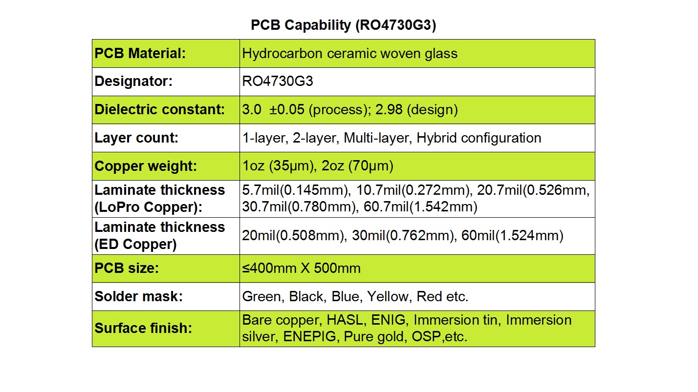
PCB Capabilities with RO4730G3


We provide fullycustomized RO4730G3 PCBs tailored to meet the specific requirements of your project. Our manufacturing services support a broad spectrum of configurations, including single-layer, double-layer, multi-layer, and hybrid stack-ups. You can select from standard copper weights such as 1oz (35µm) and 2oz (70µm), and choose from a range of laminate thickness options, including LoPro Copper (5.7mil to 60.7mil) and ED Copper (20mil to 60mil), offering unparalleled flexibility for diverse design applications.


Our production facilities can accommodate PCBs with maximum dimensions of 400mm x 500mm. To suit your aesthetic and functional preferences, we offer solder mask in various colors, including green, black, blue, yellow, and red. Additionally, a wide selection of surface finishes is available, such as bare copper, HASL (Hot Air Solder Leveling), ENIG (Electroless Nickel Immersion Gold), immersion tin, immersion silver, ENEPIG (Electroless Nickel Electroless Palladium Immersion Gold), pure gold, and OSP (Organic Solderability Preservative).


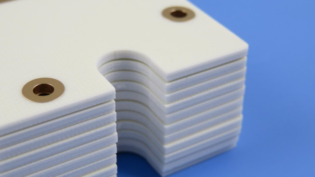
RO4730G3 PCBs


Primary Applications

The combination of stable electrical properties, thermal resilience, and cost-effectiveness makes Rogers RO4730G3 PCB particularly well-suited for radio frequency applications. Its most common application is in Cellular Base Station Antennas, where consistent high-performance signal transmission and durability are critical. However, its benefits also extend to other wireless infrastructure components, automotive radar systems, and various aerospace and defense communication modules.


By choosing Rogers RO4730G3 for your PCB needs, you are opting for a material that delivers outstanding high-frequency performance, manufacturing convenience, and long-term reliability, all at a competitive price point.


Why Choose RO4360G2 Laminates for Your Next High-Frequency PCB Project?


In the rapidly evolving world of high-frequency electronics, selecting the right printed circuit board (PCB) material is crucial to achieving optimal performance, reliability, and cost-efficiency. Rogers RO4360G2 laminates stand out as a premier choice for high-frequency applications, offering an exceptional combination of electrical properties, thermal management, and manufacturability. These glass-reinforced, hydrocarbon ceramic-filled thermoset materials are engineered to deliver superior performance while simplifying the fabrication process.


A groundbreaking feature of Rogers 4360G2 laminates is that they represent the first high dielectric constant (Dk) thermoset materials that can be processed similarly to conventional FR-4. This compatibility significantly eases the transition for designers and manufacturers looking to leverage high-Dk PCB materials without investing in new processing techniques or equipment. Furthermore, these laminates support lead-free assembly processes and provide enhanced rigidity. This improved stiffness is particularly beneficial in multi-layer board constructions, where it contributes to better dimensional stability and easier handling, ultimately reducing both material and fabrication costs.


Another notable advantage is the compatibility of RO4360G2 with other materials in the RO4000® series. It can be seamlessly integrated with RO4400™series prepregs and lower-Dk RO4000® laminates in multi-layer designs. This interoperability offers designers greater flexibility, enabling the creation of sophisticated, high-performance hybrid PCB structures tailored to specific application requirements.


Key Features of RO4360G2 High Frequency Laminates


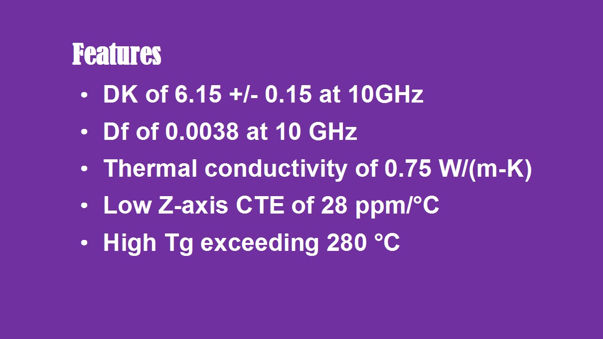
Key Features of RO4360G2


The RO4360G2 substrate boasts a high dielectric constant (Dk) of 6.15, with a design Dk of 6.4. This high Dk allows designers to reduce the physical dimensions of circuits, which is particularly advantageous in applications where minimizing size and controlling costs are critical.


With an exceptionally low dissipation factor of 0.0038 at 10 GHz, these laminates ensure minimal signal loss and outstanding signal integrity, making them ideal for high-speed and high-frequency applications.


Thermal management is another area where RO4360G2 excels. It offers a high thermal conductivity of 0.75 W/(m·K), which facilitates efficient heat dissipation away from critical components, thereby enhancing the overall reliability and longevity of the circuit.


The RO4360G2 material also exhibits a low Z-axis coefficient of thermal expansion (CTE) of 28 ppm/°C. This property ensures dimensional stability under thermal stress and significantly improves the reliability of plated through-hole (PTH) interconnections.


Finally, the RO4360G2 PCB features a high glass transition temperature (Tg) exceeding 280°C as measured by TMA (Thermomechanical Analysis). This high Tg enhances the material’s durability and performance stability even in the most demanding operating environments.


PCB Manufacturing Capabilities with RO4360G2


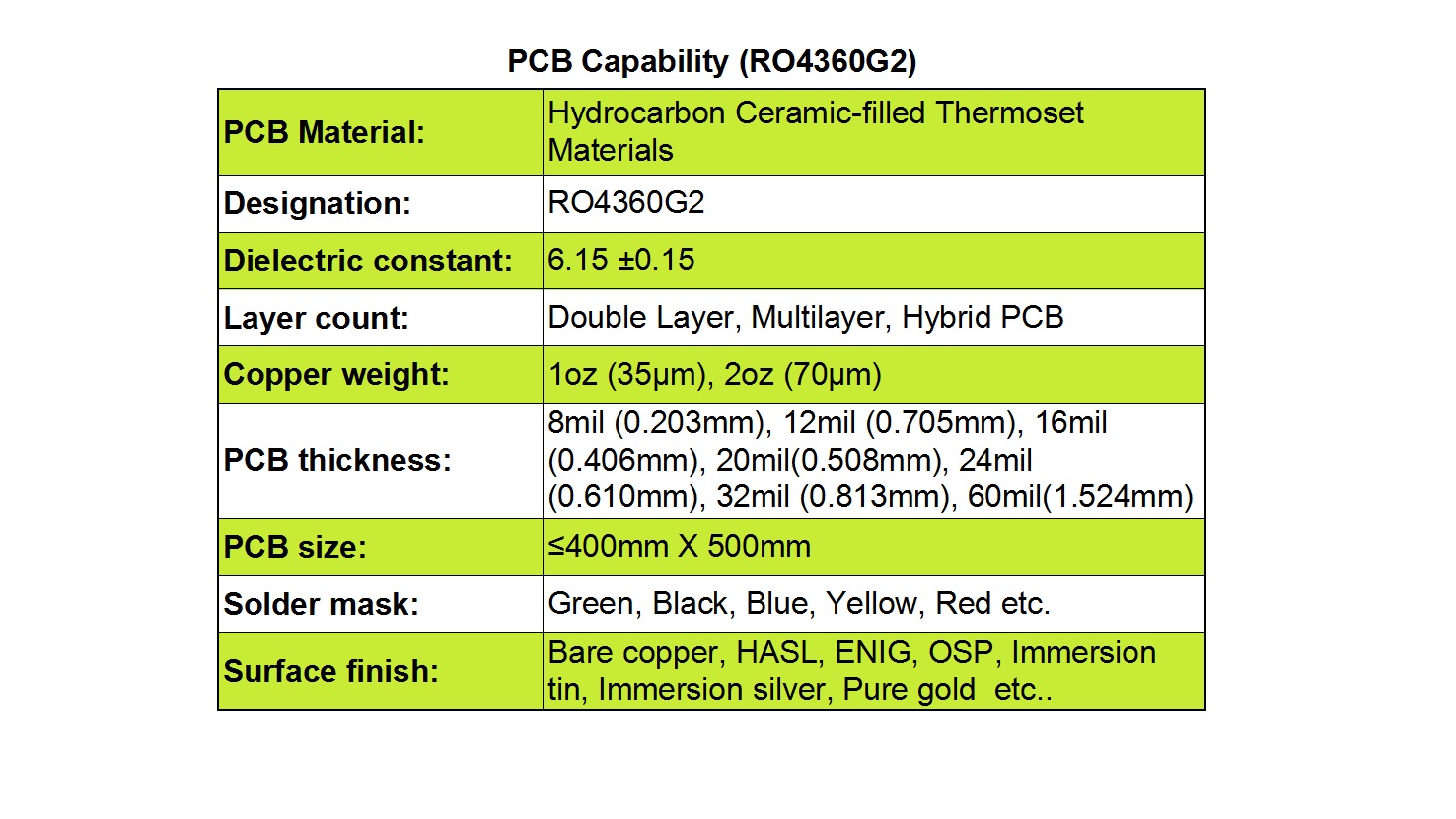
PCB Manufacturing Capabilities with RO4360G2


Our state-of-the-art manufacturing facilities are fully equipped to produce a wide variety of PCBs using RO4360G2 laminates. We specialize in manufacturing double-layer, multi-layer, and hybrid PCBs, enabling us to meet diverse design complexities and performance requirements.


We offer flexible copper weight options, including 1oz (35µm) and 2oz (70µm), allowing you to optimize current carrying capacity and signal performance based on your specific design needs.


A comprehensive range of standard thicknesses is available, such as 8mil (0.203mm), 12mil (0.305mm), 16mil (0.406mm), 20mil (0.508mm), 24mil (0.610mm), 32mil (0.813mm), and 60mil (1.524mm), providing the flexibility to meet various mechanical and electrical constraints.


Our production capabilities support PCB sizes up to 400mm x 500mm, accommodating both compact and larger form factor designs.


To suit both functional and aesthetic preferences, we provide a wide selection of solder mask colors, including green, black, blue, yellow, red, and others.


We also offer an extensive array of surface finishes, including Bare Copper, HASL (Hot Air Solder Leveling), ENIG (Electroless Nickel Immersion Gold), OSP (Organic Solderability Preservative), Immersion Tin, Immersion Silver, and Pure Gold, ensuring the optimal finish for your application’s performance and reliability needs.


RO4360G2 high-frequency PCBs


Typical Applications

RO4360G2 high-frequency PCBs are widely used in demanding RF and wireless communication applications. Common uses include base station power amplifiers and small cell transceivers, where their excellent electrical properties and thermal performance are essential for ensuring signal clarity, power efficiency, and long-term reliability in critical infrastructure.


Why Choose Rogers RO3210 PCB for High-Frequency and Thermally Demanding Applications?


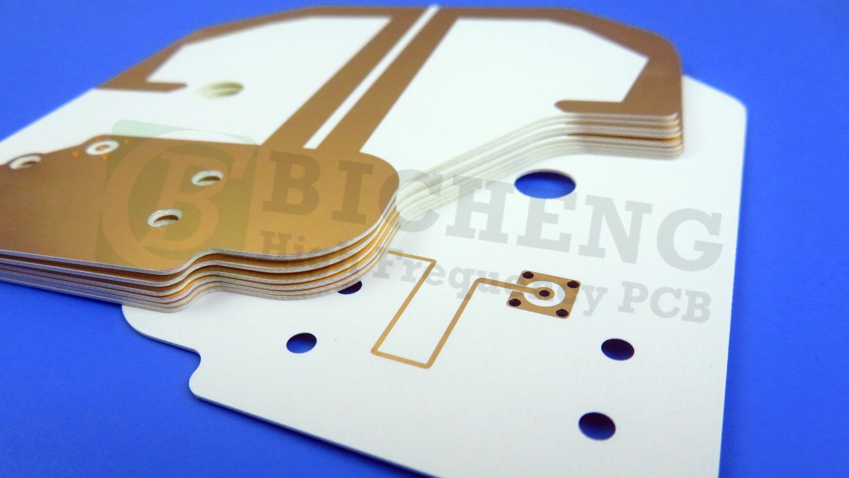
In the world of high-frequency PCB design, selecting the right substrate material is crucial for achieving optimal electrical performance, thermal management, and mechanical reliability. Rogers Corporation’s RO3210 high-frequency circuit materials stand out as an exceptional choice for demanding applications ranging from automotive radar to satellite communications. As an integral member of the renowned RO3000 series, Rogers RO3210 combines ceramic-filled construction with woven fiberglass reinforcement, delivering superior high-frequency characteristics and enhanced mechanical stability at a highly competitive cost.


Superior Electrical and Thermal Properties

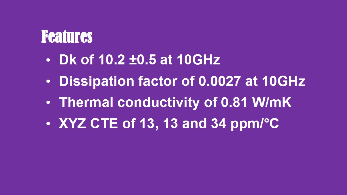
One of the most significant advantages of Rogers 3210 is its stable and relatively high dielectric constant (Dk) of 10.2, maintained within a tight tolerance of±0.5. This consistency allows RF designers to develop more compact circuit layouts, supporting the ongoing trend toward miniaturization in electronic devices without compromising electrical integrity. Moreover, its low dissipation factor of 0.0027 at 10 GHz ensures minimal signal loss and reduced distortion, which is essential for maintaining signal quality in high-speed and high-frequency applications.


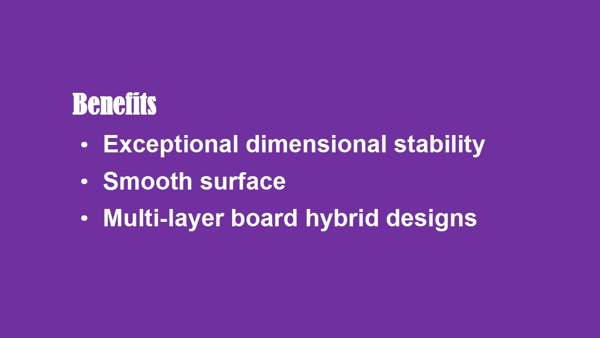
RO3210 PCB bebefits


Thermal management is another critical area where RO3210 excels. With a thermal conductivity of 0.81 W/m/K, this material effectively dissipates heat, reducing the risk of overheating in power-intensive applications. Its low coefficient of thermal expansion (CTE) across the X, Y, and Z axes further enhances reliability by minimizing dimensional changes under thermal stress, thereby supporting solder joint integrity and long-term operational stability.


RO3210 features


Enhanced Mechanical Stability and Manufacturing Precision

RO3210 is engineered for exceptional dimensional stability, which significantly improves manufacturing yield and product consistency. This stability is particularly beneficial in multi-layer and hybrid PCB constructions, where alignment accuracy is paramount. The material’s smooth surface finish allows for finer and more precise etching of conductor traces, enabling the production of intricate circuit patterns with high accuracy. This capability is indispensable for advanced designs such as microstrip patch antennas and high-density interconnect (HDI) boards.


Additionally, RO3210 laminates are compatible with epoxy-based multi-layer hybrid designs, providing designers with greater flexibility in creating complex, high-performance systems that integrate both RF and digital sections. This versatility makes it an ideal substrate for sophisticated applications that demand a blend of high frequency operation and robust mechanical properties.


Customized PCB Capabilities with RO3210 Material


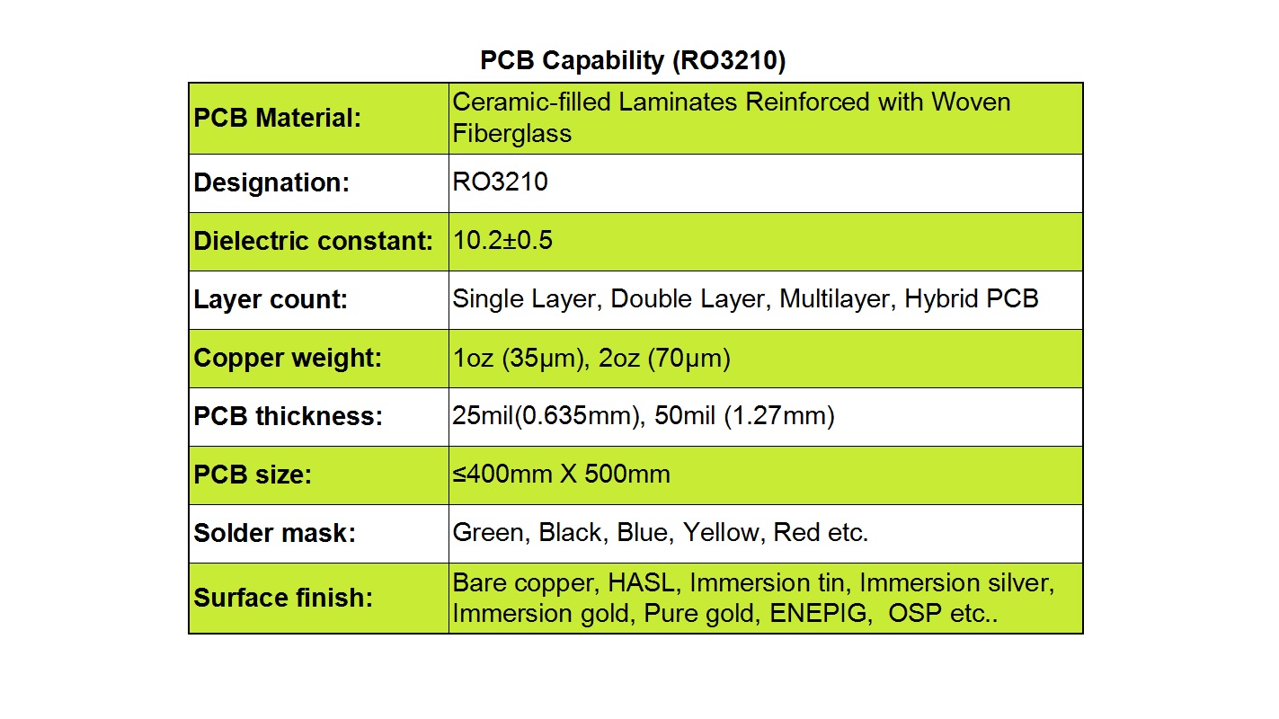
Customized PCB Capabilities with RO3210 Material


Our manufacturing services fully leverage the benefits ofRogers RO3210 to produce high-frequency PCBs tailored to your specific requirements. We support a broad spectrum of design complexities—from simple single-layer boards to advanced multi-layer and hybrid assemblies. With two standard copper weight options—1 oz (35 µm) and 2 oz (70 µm)—we help you balance current carrying capacity and signal loss based on your application needs.


We also offer two standard thicknesses: 25 mils (0.635 mm) and 50 mils (1.27 mm), providing further flexibility in impedance control and mechanical design. Our production facilities can accommodate boards up to 400 mm×500 mm in size, making us well-equipped for both compact modules and larger form-factor designs.


To enhance assembly compatibility and end-use performance, we provide a wide selection of solder mask colors (including green, black, blue, yellow, and red) and a comprehensive range of surface finishes such as HASL, immersion silver, immersion gold, ENEPIG, OSP, and bare copper.


Rogers RO3210 PCBs


Key Application Areas

Rogers RO3210 PCBs are widely employed in industries where high frequency, thermal stability, and signal integrity are non-negotiable. Common applications include:


  • Automotive radar and collision avoidance systems
  • GPS antennas and telematics modules
  • Wireless infrastructure including 5G base stations
  • Microstrip and patch antennas for communication systems
  • Direct broadcast satellite (DBS) receivers


Other RF and microwave circuits requiring stable performance under varying operating conditions


Partner with a Specialist

If you are looking for a reliable PCB supplier with expertise in high-frequency materials like Rogers RO3210, we invite you to collaborate with us. We provide end-to-end support—from material selection and design advice to manufacturing and testing—ensuring that your boards meet the highest standards of performance and reliability.


Contact us today to discuss your project requirements and discover how RO3210 can enhance your next high-frequency PCB design.


Why Choose TLX-8 for Your Next High-Frequency PCB Design? Key Features and Benefits Explained.


In the rapidly advancing world of electronics, the demand for high-frequency printed circuit boards (PCBs) that deliver consistent performance under challenging conditions is higher than ever. For engineers and designers working on cutting-edge RF and microwave applications, selecting the right substrate material is paramount to the success and reliability of the entire system. Enter the Taconic TLX-8 PCB—a superior PTFE-based microwave substrate engineered to excel where ordinary materials fall short.


Introduction to TLX-8: Engineered for Excellence

Taconic TLX-8 is a high-performance polytetrafluoroethylene (PTFE) composite material, uniquely reinforced with a high-volume fiberglass weave. This strategic reinforcement provides exceptional mechanical durability, making TLX-8 an outstanding choice for low-layer-count microwave circuit designs. Its robust construction ensures unwavering reliability across a vast spectrum of radio frequency (RF) applications, particularly those operating in demanding physical and environmental conditions.


The structural integrity offered by its fiberglass reinforcement is critical for applications where failure is not an option. TLX-8 Taconic RF PCB Circuit Board is designed to perform reliably in the most challenging scenarios, including:


Resisting mechanical creep and deformation in PCBs that are bolted to housings and subjected to extreme vibration, such as during space launch vehicles.


Enduring sustained exposure to elevated temperatures commonly found within automotive engine control modules or aerospace systems.


Demonstrating exceptional resistance to radiation, a necessity for electronics deployed in space missions.


Withstanding corrosive and unpredictable conditions at sea for naval and warship antenna systems.


Maintaining stable electrical performance across a wide operational temperature range for avionics, including altimeter substrates during flight.


Properties and Features

The TLX-8 Taconic PCB Laminates is defined by a suite of electrical and physical properties that make it a industry standout.
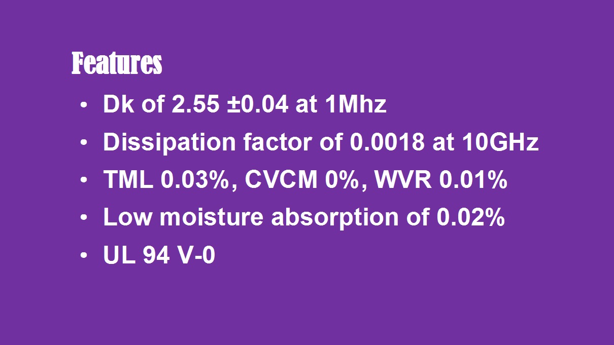
 

TLX-8 PCB Features


1)Stable Dielectric Constant:

TLX-8 boasts a low and exceptionally stable dielectric constant (Dk) of 2.55±0.04, measured at 1 MHz. This consistency is vital for maintaining signal integrity and impedance control in precise microwave designs, ensuring predictable performance across the board.


2)Minimal Signal Loss:

With an ultra-low dissipation factor (Df) of just 0.0018 at 10 GHz, TLX-8 ensures minimal energy loss as signals travel across the circuit. This translates to higher efficiency, better signal quality, and reduced heat generation in high-frequency transmission applications.


3)Superior Outgassing and Moisture Management:

TLX-8 excels in high-vacuum and space environments due to its excellent outgassing properties. It records a remarkably low Total Mass Loss (TML) of 0.03% and a Collected Volatile Condensable Materials (CVCM) value of 0.00%. Coupled with a low Water Vapor Regain (WVR) of 0.01% and a moisture absorption rate of only 0.02%, TLX-8 effectively manages humidity, preventing performance degradation in environments with fluctuating moisture levels.


4)Enhanced Safety Standards:

The material carries a UL 94 V-0 flammability rating, signifying its compliance with stringent safety standards. This makes it a safe and reliable choice for a wide array of commercial, aerospace, and defense applications.


PCB Manufacturing Capabilities with TLX-8

Our manufacturing expertise allows us to fully leverage the superior properties of TLX-8 Taconic RF PCB, offering a wide range of fabrication options to meet diverse and complex design requirements.
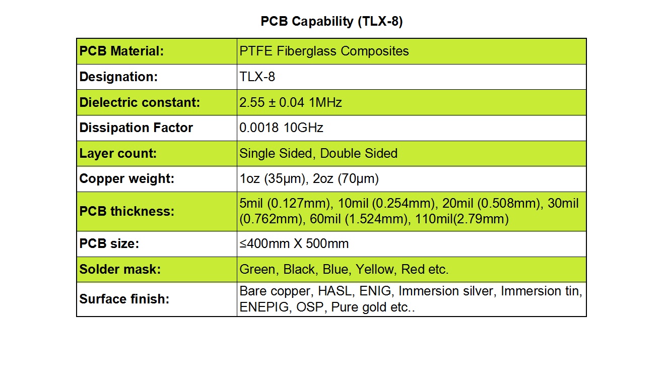

PCB Manufacturing Capabilities with TLX-8


1)Layer Construction & Copper Weights: 

We provide precision fabrication for both single-sided and double-sided PCBs, with standard copper weights ranging from 1oz (35µm) to 2oz (70µm).


2)Board Thickness:

To accommodate various design needs, we offer multiple thickness options including 5mil (0.127mm), 10mil (0.254mm), 20mil (0.508mm), 30mil (0.762mm), 60mil (1.524mm), and 110mil (2.79mm).


3)Panel Size:

Our production capabilities can accommodate PCB sizes up to 400mm x 500mm, providing ample space for larger or multi-unit designs.


4)Aesthetic Customization:

We offer a selection of solder mask colors—including green, black, blue, yellow, and red—enabling both functional performance and brand-specific aesthetics.


5)Surface Finish Options:

To suit any application need, we provide a comprehensive range of surface finishes: Bare Copper, HASL (Hot Air Solder Leveling), ENIG (Electroless Nickel Immersion Gold), Immersion Silver, Immersion Tin, ENEPIG (Electroless Nickel Electroless Palladium Immersion Gold), OSP (Organic Solderability Preservative), and Pure Gold.
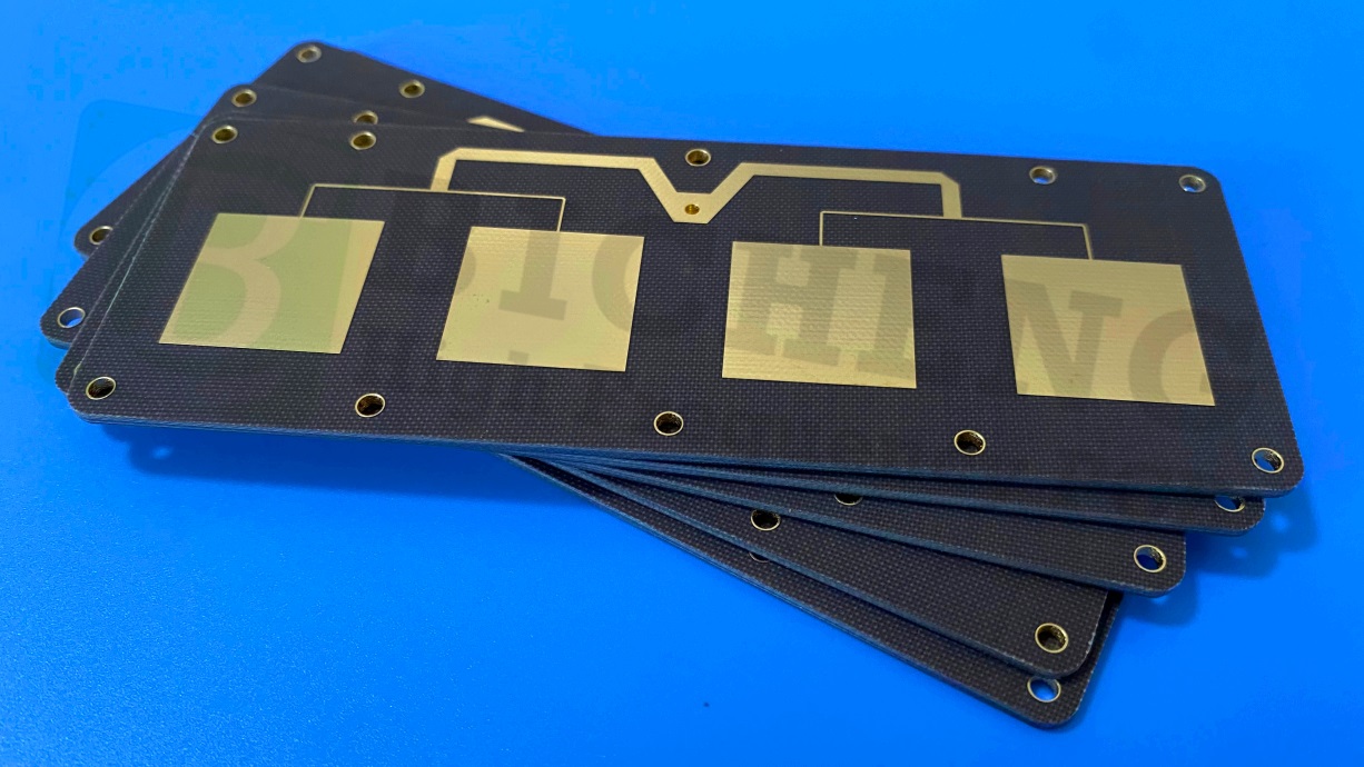

TLX-8 Taconic PCB


Diverse Applications for TLX-8 PCBs

Thanks to its reliable electrical properties and robust physical characteristics, the TLX-8 Taconic PCB is the material of choice for critical applications in several high-tech industries. It is ideally suited for:


  • Radar Systems and satellite communication equipment.
  • Mobile and Cellular Communication infrastructure.
  • High-Precision Microwave Test and measurement equipment.
  • Microwave Transmission devices and point-to-point radios.
  • Sensitive RF Components such as amplifiers, antennas, and filters.


In conclusion, the TLX-8 High Frequency PCB represents a perfect synergy of mechanical robustness and electrical excellence. Whether your project is destined for Earth's most remote locations or the vastness of space, TLX-8 provides the proven performance and reliability needed.

Why Should You Choose RO3006 Material for Your Advanced Microwave Circuit Designs?


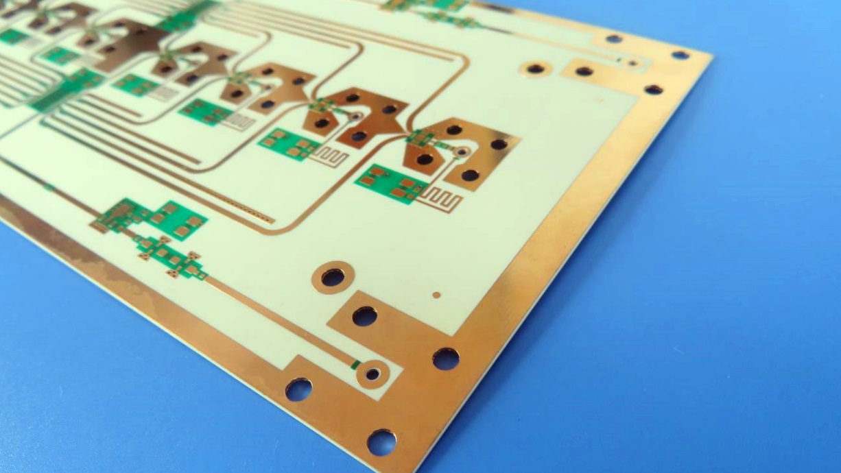
In the rapidly evolving field of high-frequency electronics, the demand for reliable and high-performance printed circuit boards (PCBs) is greater than ever. RO3006 circuit materials stand out as an exceptional solution tailored for commercial microwave and radio frequency (RF) applications. Engineered from ceramic-reinforced polytetrafluoroethylene (PTFE) composites, these substrates deliver a unique combination of electrical excellence, mechanical reliability, and cost-effectiveness. A key advantage of Rogers RO3006 lies in its stable dielectric constant across an extensive temperature spectrum. This property effectively resolves the issue of abrupt Dk variations commonly found in conventional PTFE glass materials around ambient temperature, ensuring consistent performance in real-world operating conditions.


Key Characteristics of RO3006 High-Frequency PCBs


Key Characteristics of RO3006 High-Frequency PCBs


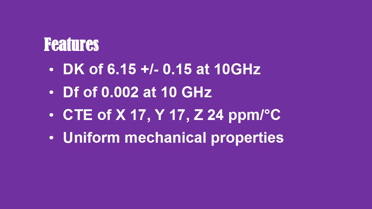
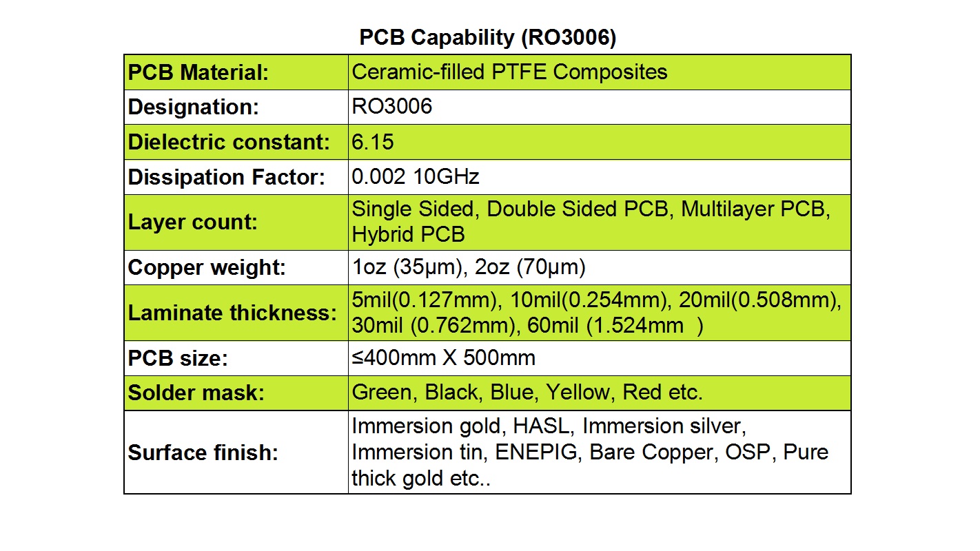
RO3006 laminates boast a dielectric constant (Dk) of 6.15 with a tight tolerance of±0.15, which allows for accurate impedance matching and ensures consistent signal integrity throughout the transmission line. This level of control is crucial for high-speed digital and high-frequency analog circuits.


Furthermore, the RO3006 material exhibits an ultra-low dissipation factor of just 0.0020 at 10 GHz, meaning minimal signal attenuation and enhanced efficiency for power-sensitive applications. This low loss characteristic makesRogers3006 an ideal candidate for designs operating in the GHz range, where preserving signal strength is paramount.


Another standout feature is its dimensional stability driven by a low coefficient of thermal expansion (CTE). The CTE values for the X, Y, and Z axes are 17 ppm/°C, 17 ppm/°C, and 24 ppm/°C, respectively. This closely matched CTE across planes significantly reduces the risk of deformation or delamination under thermal stress and helps maintain phase stability in critical applications like phased-array antennas and automotive radar systems.


Additionally, RO3006 is part of the broader RO3000® Series, which ensures uniform mechanical and processing characteristics. This compatibility simplifies integration into complex multi-layer stack-ups and hybrid assemblies, providing designers and manufacturers with greater flexibility without compromising reliability or manufacturability.


Advanced PCB Manufacturing Capabilities for RO3006

We support a comprehensive range of PCB structures, including single-sided, double-sided, multi-layer, and hybrid construction—enabling optimized performance for both standalone RF modules and mixed-signal systems.


PCB Manufacturing Capabilities for RO3006


To suit various current-carrying requirements and high-frequency effects, we provide copper weights of 1oz (35µm) and 2oz (70µm). Laminate thickness is available from 5mil (0.127mm) up to 60mil (1.524mm), supporting a wide array of design constraints from thin, flexible configurations to robust, thick-board applications.


Our maximum panel size of 400mm x 500mm allows for larger layouts or efficient panelization for cost-effective production. We also offer a selection of solder mask colors—green, black, blue, yellow, red, and others—so you can align aesthetics with functional branding or identification requirements.


For surface finish, customers can choose from immersion gold (ENIG), HASL, immersion silver, immersion tin, ENEPIG, bare copper, OSP, pure thick gold, and other treatments. Each option is tailored to specific needs such as solderability, shelf life, compatibility with gold wire bonding, or high-frequency performance.


RO3006 high frequency PCBs


Typical Applications of RO3006 HF PCBs

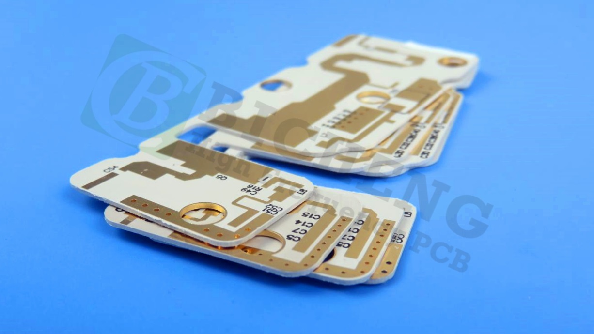
RO3006 high frequency PCBs are widely used across industries where signal integrity and thermal resilience are critical. Common use cases include:


  • Automotive radar systems (e.g., adaptive cruise control, collision avoidance)
  • Global Positioning Satellite (GPS) and other satellite communication antennas
  • Cellular telecommunications infrastructure such as power amplifiers and base station antennas
  • Patch antennas and RF transceivers for wireless communication
  • Direct broadcast satellite (DBS) receivers and other high-frequency consumer electronics


By leveraging the superior material properties of RO3006 and our advanced manufacturing expertise, your high-frequency PCB projects can achieve new levels of performance, integration, and reliability.