RJ45 and RJ11 are two of the most common modular connector types, but they serve very different purposes. Despite their similar appearance, confusing them can lead to equipment damage, signal problems, and failed installations. This article provides a clear, technical comparison to help you identify, use, and specify the correct connector for your application.

The search term "RJ45 vs RJ11" receives approximately 8,100 searches per month on Google, making it one of the highest-traffic connector comparison queries. This guide answers that question definitively.

RJ45 vs RJ11: Quick Comparison Table

Feature RJ45 RJ11
Standard IEC 60603-7 FCC Part 68
Configuration 8P8C (8 positions, 8 contacts) 6P2C or 6P4C (6 positions, 2-4 contacts)
Contact count 8 2 or 4 (rarely 6)
Width 11.68 mm 9.65 mm
Primary use Ethernet networking (10/100/1G/10G) Telephone landlines, DSL, modem cables
Max speed 10 Gbps (10GBase-T) ~24 Mbps (VDSL2)
Pairs used 4 (for Gigabit+) 1-2
Voltage rating Up to 60V DC (PoE) ~48V DC (telephone)
PoE support Yes (802.3af/at/bt, up to 90W) No
Can fit RJ11 jack? No (too wide) N/A
Can fit RJ45 jack? N/A Yes (but not recommended)
Typical cable Cat5e/Cat6/Cat6a/Cat7 twisted pair Flat silver satin or twisted pair

Physical Differences: How to Tell Them Apart

Size and Contact Count

The most obvious difference is size. RJ45 has 8 gold contact pins visible on the top of the plug, while RJ11 has only 2 or 4 (sometimes 6). RJ45 is also approximately 2mm wider than RJ11. If you line up both connectors side by side, the RJ45 is noticeably larger.

Latch Shape

Both connectors use a spring-loaded latch (tab) for retention, but the RJ45 latch is wider and more robust. The RJ11 latch is narrower and more fragile. An RJ11 plug can physically fit into an RJ45 jack because the latch will engage, but the smaller RJ11 contacts will only touch the outermost RJ45 jack contacts, and the plastic housing may not seat properly, potentially damaging the jack.

Cable Type

RJ45 connectors are designed for round, twisted-pair cable (Cat5e through Cat8), typically 22-26 AWG. RJ11 connectors are designed for flat silver-satin telephone cable or round twisted-pair, typically 24-26 AWG with only 2-4 conductors.

Functional Differences: What Each Connector Does

RJ45: The Ethernet Workhorse

RJ45 is the standard connector for Ethernet networking. It carries data at speeds from 10 Mbps to 10 Gbps over twisted-pair copper cable. In modern applications, RJ45 connectors often include integrated magnetics (transformers and common-mode chokes) for signal isolation, EMI suppression, and Power over Ethernet (PoE) support up to 90 watts.

RJ11: The Telephone Connector

RJ11 is the standard connector for analog telephone lines. It carries voice signals and low-speed data (DSL, modem) over 1-2 twisted pairs. RJ11 is not designed for high-speed data networking and does not support PoE. In modern installations, RJ11 is increasingly being replaced by RJ45 for VoIP phones and IP-based telephony.

Can You Plug an RJ11 into an RJ45 Jack?

Physically, yes. An RJ11 plug is narrow enough to fit into an RJ45 jack, and the latch will click into place. However, this is strongly discouraged for several reasons:

  • Only 2-4 of the 8 RJ45 jack contacts will be engaged, which may not align with the correct pins for Ethernet.
  • The RJ11 plug's plastic housing does not fill the RJ45 jack opening, leaving the unused contacts exposed to dust and contamination.
  • Repeated insertion of RJ11 plugs can bend or damage the inner contacts of an RJ45 jack, causing future Ethernet connections to fail.
  • If PoE is active on the RJ45 port, the misaligned RJ11 contacts could create a short circuit, potentially damaging the telephone or the PoE switch.
⚠ Best Practice:Always use the correct connector type. If you need to connect a telephone to an RJ45 wall plate, use an RJ45-to-RJ11 adapter designed for this purpose.

Pinout Comparison

RJ45 Pinout (T568B Wiring)

Pin Color (T568B) Function (10/100Base-T) Function (1000Base-T)
1 White/Orange TX+ BI_DA+
2 Orange TX- BI_DA-
3 White/Green RX+ BI_DB+
4 Blue Not used BI_DC+
5 White/Blue Not used BI_DC-
6 Green RX- BI_DB-
7 White/Brown Not used BI_DD+
8 Brown Not used BI_DD-

RJ11 Pinout (6P4C, 2-Pair)

Pin Color Function
1 N/A (not connected in 6P2C) Unused
2 Black (or Yellow) Ring (Line 2)
3 Red Tip (Line 1)
4 Green Ring (Line 1)
5 Yellow (or Black) Tip (Line 2)
6 N/A (not connected in 6P2C) Unused

Application Comparison

Application RJ45 RJ11
Ethernet networking Yes (primary) No
PoE (power over Ethernet) Yes No
Analog telephone No (use RJ45 for VoIP) Yes (primary)
DSL/broadband modem Possible but uncommon Yes (traditional)
Industrial Ethernet Yes No
Smart home / IoT Yes (wired) No
Data center Yes (primary) No

VITALCONN RJ45 Solutions

VITALCONN Electronics manufactures 163+ ICM RJ45 connector models, covering the full range of Ethernet applications from 10/100Base-T to 10GBase-T. While we do not manufacture RJ11 connectors, our RJ45 product line is designed to serve all networking and telephony applications that have migrated to IP-based infrastructure.

Why choose VITALCONN RJ45?

  • 163+ ICM RJ45 models with speeds from 10/100M to 10G
  • Full PoE support: IEEE 802.3af (15.4W) to 802.3bt Type 4 (90W)
  • All mounting types: DIP, SMT, Press-Fit
  • Configurations: 1x1, 1xN, 2xN stacked, Combo
  • ARP cross-reference: 26 pin-to-pin replacements for Pulse, BelFuse, TE, Molex, Amphenol, and more
  • 30-40% cost advantage vs. major brands, with 2-4 week lead times
💡 Tip:VITALCONN's ARP (Auto Reference Platform) covers 26 RJ45 cross-reference replacements across 11 brands including Pulse, BelFuse, TE, Molex, and Amphenol — offering 30-40% cost savings with 2-4 week lead times versus 12-24 weeks for original parts.

Frequently Asked Questions (FAQ)

Can I use RJ11 instead of RJ45 for Ethernet?
No. RJ11 only has 2-4 contacts and cannot support the 4-pair connection required for Gigabit Ethernet. Even for 10/100Base-T (which uses only 2 pairs), RJ11 lacks the shielding and impedance control needed for reliable Ethernet. Always use RJ45 for networking.
Why is RJ45 bigger than RJ11?
RJ45 has 8 contact positions (8P8C) to support 4 twisted pairs for Gigabit Ethernet, while RJ11 has only 6 positions with 2-4 contacts (6P2C/6P4C) for 1-2 telephone pairs. The additional contacts require a wider connector body.
Can an RJ11 plug damage an RJ45 jack?
Yes. The RJ11 plug is narrower than the RJ45 jack, so it does not properly seat in the jack. Repeated insertions can bend the inner contacts of the RJ45 jack, and if PoE is active, the misaligned contacts could short-circuit.
Is RJ45 compatible with telephone lines?
Not directly. Telephone lines use RJ11 connectors. However, VoIP (Voice over IP) phones use RJ45 for Ethernet connectivity, so modern IP telephone systems do use RJ45. If you need to connect an analog telephone to an RJ45 port, use an RJ45-to-RJ11 adapter.
What is the speed difference between RJ45 and RJ11?
RJ45 can support up to 10 Gbps (10GBase-T) over Cat6a cable. RJ11, when used for DSL, typically supports up to 24 Mbps (VDSL2). The speed difference is due to the number of twisted pairs (4 vs 1-2), shielding, and impedance control.
Need RJ45 Connectors for Your Next Project?
VITALCONN manufactures 163+ ICM RJ45 models with ISO 9001 certified quality. Request free samples or a custom quote today.
Explore RJ45 Connectors Request Samples

As data center bandwidth scales from 400G to 800G and beyond, the power dissipation of optical transceiver modules is rising dramatically. A single QSFP-DD 800G transceiver can consume 15-20W, and a 48-port switch may host transceivers generating over 700W of heat. Without proper thermal management, transceiver temperatures exceed safe operating limits, causing bit errors, reduced lifetime, and thermal shutdown. The SFP cage heatsink is the primary thermal management component between the transceiver and the ambient air. This article explains SFP cage heatsink design principles, thermal performance metrics, heatsink types, and how VITALCONN's thermal-optimized cages achieve 5-8°C lower transceiver core temperature.

Why Transceiver Thermal Management Matters

Metric Effect of High Temperature
Bit Error Rate (BER) Increases exponentially above 70°C junction temperature
Module lifetime Halved for every 10°C increase above 70°C (Arrhenius equation)
Optical output power Decreases with temperature, affecting link budget
Receiver sensitivity Degrades with temperature, reducing margin
Wavelength drift Laser wavelength shifts with temperature, causing DWDM channel crosstalk
Thermal shutdown Transceiver shuts down above 85°C to prevent damage

The SFF-8431 and SFF-8636 specifications define a maximum case temperature of 70°C for most transceiver modules. The cage heatsink must keep the transceiver case below this limit under the specified ambient temperature and airflow conditions.

The Heat Transfer Path in SFP Cages

Heat generated by the transceiver module's laser driver and electronic components follows a specific path to the ambient air:

  1. Step 1 - Heat generation: Transceiver IC and laser generate heat inside the module package.
  2. Step 2 - Conduction to case: Heat conducts through the transceiver's metal case (typically cast zinc or aluminum).
  3. Step 3 - Case-to-heatsink contact: Heat transfers from the transceiver case to the cage's integrated heatsink or top surface through direct contact.
  4. Step 4 - Conduction through heatsink: Heat spreads through the heatsink fins via thermal conduction.
  5. Step 5 - Convection to air: Forced air from the system fans flows over the heatsink fins, carrying heat away through convection.

The thermal bottleneck is typically at Step 3 (case-to-heatsink contact). The contact area, contact pressure, and thermal interface material (if any) determine the thermal resistance at this interface.

SFP Cage Heatsink Types

Type Description Thermal Performance Best For
No heatsink (bare cage) Cage without heatsink; transceiver cools by natural convection Poor (θj-a > 30°C/W) Low-power modules ≤ 1.5W (SFP 1G)
Stamped top plate Thin stamped metal plate on cage top Limited (θj-a 20-30°C/W) SFP/SFP+ up to 2.5W
Integrated stamped heatsink Stamped aluminum fins integrated into cage top Moderate (θj-a 12-20°C/W) SFP+/SFP28 up to 3.5W
Extruded aluminum heatsink Extruded fin array bolted or clipped to cage Good (θj-a 8-15°C/W) QSFP+/QSFP28 up to 5W
High-performance extruded heatsink Large extruded fins with optimized spacing and base thickness Excellent (θj-a 5-10°C/W) QSFP-DD/OSFP up to 20W
Vapor chamber + heatsink Vapor chamber base with fin stack Best (θj-a 3-7°C/W) Future 1.6T modules > 20W

Key Heatsink Design Factors

Fin Spacing and Density

Fin spacing must balance surface area against airflow resistance. Closely spaced fins provide more surface area but create higher air pressure drop, reducing airflow in systems with limited fan static pressure. The optimal fin spacing for forced air (2-5 m/s) is typically 2-3mm. For natural convection, wider spacing (5-8mm) is better.

Heatsink Base Thickness

The heatsink base spreads heat from the transceiver contact area to the fins. A thicker base improves heat spreading but adds weight and cost. For QSFP-DD modules, a base thickness of 3-5mm is typical. VITALCONN uses aluminum alloy 6063-T5 with optimized base thickness for each cage type.

Airflow Direction

The heatsink fin orientation should align with the system airflow direction. In most switches, air flows from front (where transceivers are) to back (where exhaust fans are). The fins should run parallel to the airflow direction. Perpendicular fins create turbulence and pressure drop, reducing cooling efficiency.

Contact Pressure and Thermal Interface

The thermal resistance between the transceiver case and the heatsink depends on contact pressure and surface flatness. A contact pressure of 20-50 PSI is typical. Some designs use a thin thermal pad (0.5-1.0mm, k=1-6 W/mK) to fill microscopic air gaps between the surfaces. VITALCONN's cages are designed with precise dimensional tolerances to ensure consistent contact pressure without a thermal pad.

Bottom Airflow Channels

VITALCONN's thermal-optimized cages include bottom airflow channels that allow cool air to reach the underside of the transceiver. Standard cages have a solid bottom, blocking airflow to half of the transceiver surface. Bottom channels can reduce transceiver temperature by 2-4°C.

Thermal Performance Metrics

Metric Definition Target Value
θj-a (°C/W) Temperature rise per watt from junction to ambient < 10°C/W for QSFP-DD
θc-a (°C/W) Temperature rise per watt from case to ambient < 8°C/W
Case temperature Temperature at transceiver case surface < 70°C (SFF spec)
Thermal margin Difference between case temp and 70°C limit ≥ 5°C margin recommended
Airflow requirement Minimum linear airflow speed for rated cooling 1.5-5 m/s (300-1000 LFM)

VITALCONN Thermal-Optimized SFP Cages

VITALCONN's thermal-optimized SFP cages incorporate three design innovations that together achieve 5-8°C lower transceiver core temperature compared to standard cages:

  1. Top venting: Precision-stamped vent holes on the cage top allow cool air to directly contact the transceiver case, bypassing the heatsink thermal resistance.
  2. Bottom airflow channels: Structured bottom openings allow airflow to reach the underside of the transceiver, cooling the PCB and components that are not in contact with the heatsink.
  3. Optimized heatsink geometry: Extruded aluminum heatsinks with optimized fin spacing (2.5mm), base thickness (4mm for QSFP-DD), and airflow-aligned fin orientation maximize convective heat transfer.
Lab Result: In VITALCONN lab testing, a QSFP28 transceiver at 3.5W power in a standard cage reached 68°C case temperature at 3 m/s airflow. The same transceiver in a VITALCONN thermal-optimized cage reached 62°C — a 6°C improvement that doubles the expected module lifetime.

Thermal Challenges at 800G and Beyond

QSFP-DD 800G transceivers consume 15-20W, nearly 5x the power of a 100G QSFP28 module. In a 48-port 800G switch, the total transceiver power can exceed 700W. This requires:

  • Larger heatsinks with more fin surface area (typically 40-60 fins vs 15-25 for QSFP28)
  • Higher system airflow (5-8 m/s vs 2-3 m/s for 100G)
  • Vapor chamber or heat pipe technology for the highest-power modules
  • Liquid cooling integration for 1.6T and beyond (future)

VITALCONN's OSFP and QSFP-DD cages are designed for the 800G thermal envelope, with extruded heatsinks featuring 50+ fins, 5mm base thickness, and both top and bottom airflow optimization. Our thermal lab can simulate your specific airflow and power conditions to recommend the optimal cage and heatsink combination.

Frequently Asked Questions (FAQ)

What temperature should an SFP transceiver not exceed?

Per SFF-8431 (SFP/SFP+/SFP28) and SFF-8636 (QSFP) specifications, the maximum case temperature is 70°C for commercial-grade modules. Exceeding this temperature increases bit error rate, reduces laser lifetime, and can trigger thermal shutdown at 85°C.

How much heat does an SFP+ transceiver generate?

A typical SFP+ (10G) transceiver consumes 1.0-1.5W. This can be managed with a simple stamped heatsink or even without a heatsink in well-ventilated systems. QSFP28 (100G) modules consume 3.5-4.5W and require an extruded heatsink. QSFP-DD (800G) modules consume 15-20W and require high-performance thermal management.

What is theta-j-a and why does it matter for SFP cages?

Theta-j-a (junction-to-ambient thermal resistance) measures how many degrees Celsius the transceiver junction rises per watt of power dissipated. A lower theta-j-a means better thermal performance. For QSFP-DD cages, a theta-j-a below 10°C/W is typically required to keep the case below 70°C at 20W power and 40°C ambient.

Can I use a VITALCONN heatsink with a TE Connectivity cage?

VITALCONN's SFP cage cross-reference (ARP) platform provides 27 pin-to-pin replacements for TE Connectivity cages. The replacement cages come with VITALCONN's own heatsink designs, which are thermally optimized. If you need to replace a TE cage, contact sales@vitalconn.com with your TE part number for a thermal-equivalent VITALCONN model.

Do I need a thermal pad between the transceiver and heatsink?

It depends on the flatness of the heatsink base and transceiver case. VITALCONN cages are manufactured with tight flatness tolerances (typically < 0.1mm), allowing direct metal-to-metal contact without a thermal pad. This provides lower thermal resistance than pad-based solutions. If your transceiver has an uneven case surface, a thin thermal pad (0.5mm, k ≥ 3 W/mK) can improve contact.

What airflow speed do I need for QSFP-DD 800G?

For QSFP-DD 800G transceivers at 15-20W, a minimum linear airflow of 5 m/s (1000 LFM) is typically required with a high-performance heatsink. VITALCONN's thermal-optimized cages can achieve adequate cooling at 4 m/s due to the top and bottom airflow channels that improve heat transfer efficiency.

Need Thermal-Optimized SFP Cages?

VITALCONN manufactures 102 SFP/QSFP cage models with thermal-optimized designs.
Request free samples or a thermal simulation for your next project.

A LAN transformer module is the unsung hero of every Ethernet connection, silently isolating signals, suppressing noise, and ensuring reliable data transmission from 10Mbps to 10Gbps. As a manufacturer of 39 LAN transformer models with isolation ratings up to 6kV, VITALCONN Electronics has spent 14 years perfecting the design and production of these critical components. This guide shares our manufacturing expertise to help you understand LAN transformer modules from the inside out.

Whether you are designing a 10 Gigabit Ethernet switch, a Power over Ethernet (PoE++) camera, or an industrial gateway, the LAN transformer module you select directly impacts signal integrity, EMI compliance, and system reliability. This comprehensive guide covers everything from basic working principles to advanced selection criteria.

What You Will Learn1) LAN transformer module fundamentals and working principles 2) Complete type classification (discrete vs integrated, SMT vs DIP) 3) Key specifications (isolation, insertion loss, return loss, crosstalk) 4) PoE/PoE+/PoE++ magnetics requirements 5) Common mode choke and EMI suppression 6) How to choose the right LAN transformer module 7) Common design mistakes 8) VITALCONN's 39-model product line

What Is a LAN Transformer Module? A Manufacturer's Definition

A LAN transformer module is a magnetic component that provides signal isolation and impedance matching between a PHY (Physical Layer) chip and the Ethernet cable (twisted pair). It consists of multiple transformers and common mode chokes integrated into a single package, typically 6 to 88 pins. The LAN transformer module ensures that differential Ethernet signals are transmitted with minimal distortion while blocking common mode noise and providing galvanic isolation.

Core Components Inside a LAN Transformer Module

  • Isolation Transformer: Transforms the differential signal voltage level and provides galvanic isolation (typically 1500VAC minimum).
  • Common Mode Choke (CMC): Suppresses common mode EMI noise on the twisted pair, preventing radiation from the cable.
  • Center Tap (CT): Provides DC power injection/extraction for PoE applications (IEEE 802.3af/at/bt).
  • Impedance Matching: Matches the 100-ohm impedance of twisted pair cable to the PHY output impedance.
  • Auto Transformer (optional): Provides a defined return path for signal current, reducing EMI emissions.

Why Ethernet Needs a LAN Transformer Module

Without a LAN transformer module, a PHY chip cannot drive an Ethernet cable directly. The module provides three essential functions that cannot be integrated into the PHY chip:

  1. Galvanic isolation: IEEE 802.3 requires 1500VAC isolation between PHY and cable for safety and surge protection.
  2. Common mode noise rejection: CMC blocks noise that would otherwise radiate from the cable, failing FCC/CISPR EMI limits.
  3. Impedance matching: The module matches the PHY's output to 100 ohm differential impedance, minimizing signal reflections.

How a LAN Transformer Module Works: Signal Path Explained

Understanding the LAN transformer module's working principle requires tracing the signal path from PHY to cable. Here is what happens when a data packet is transmitted:

Signal Path: TX Direction (PHY to Cable)

Step 1: PHY generates a differential voltage signal on TX+ and TX- pins.

Step 2: Signal enters the LAN transformer module's primary winding (PHY side).

Step 3: Transformer couples the signal to the secondary winding (cable side) via magnetic flux.

Step 4: Galvanic isolation is maintained between primary and secondary (no DC path).

Step 5: Signal passes through the common mode choke, which attenuates common mode noise.

Step 6: Differential signal exits to the RJ45 jack and onto the twisted pair cable.

PoE Power Injection via Center Tap

In PoE applications, DC power (48V) is injected through the transformer's center tap. The LAN transformer module must be designed to handle the DC current without saturating the core. VITALCONN's PoE++ magnetics are rated for 600mA per channel (IEEE 802.3bt Type 4, 90W), with gapped cores that prevent saturation under DC bias.

LAN Transformer Module Types: Complete Classification

By Integration Level

Type Description Advantages Best For
Discrete Magnetics Standalone transformer module, separate from RJ45 Lower cost, flexible PCB layout Space-constrained designs
Integrated (ICM) Transformer built into RJ45 connector (ICM RJ45) Fewer components, simpler assembly Most common Ethernet devices
Phy-Side Magnetics Transformers on PHY side, between PHY and connector Shorter high-speed traces High-density switch/router designs

By Speed Rating

Speed Frequency Turns Ratio VITALCONN Models
10/100Base-TX up to 100MHz 1CT:1CT or 1:1 TG series (6-48 pin)
1000Base-T (Gigabit) up to 100MHz, 4 pairs 1CT:1CT TH series (16-48 pin)
2.5G/5GBase-T up to 250/500MHz 1CT:1CT TK series (high-freq)
10GBase-T up to 500MHz 1CT:1CT TK-10G series

By Mounting Type

Mounting Assembly Advantages VITALCONN Series
SMT Reflow soldering High-speed automated assembly TG-SMT, TH-SMT
DIP Through-hole wave soldering Mechanical robustness, lower cost TG-DIP, TH-DIP

Key Specifications: What to Look for in a LAN Transformer Module

Selecting a LAN transformer module requires understanding several critical specifications. VITALCONN tests every parameter on 100% of production units.

Electrical Specifications

Parameter Typical Spec Why It Matters Test Method
Isolation Voltage 1500-5000 VAC Safety compliance, surge protection Hi-Pot test, 1 minute
Insertion Loss <1.0dB @ 100MHz (1G) Signal attenuation; lower = better Network analyzer, S21
Return Loss >18dB @ 100MHz (1G) Signal reflection; higher = better Network analyzer, S11
Crosstalk (NEXT) >40dB @ 100MHz Inter-channel interference Network analyzer, near-end
Common Mode Rejection >40dB @ 100MHz EMI suppression capability CMRR measurement
DC Resistance (CT) <1.0 ohm per winding PoE power loss; lower = better DC milliohmmeter
Hi-Pot Leakage <2mA at 1500VAC Safety isolation verification Hi-Pot tester
Manufacturer's Real Data: Insertion LossVITALCONN's 10G LAN transformer modules achieve <0.8dB insertion loss at 500MHz, verified by Keysight network analyzer. This is 20% better than the IEEE 802.3ae maximum of 1.0dB, meaning less signal attenuation and longer achievable cable distances.

Environmental Specifications

Parameter VITALCONN Standard Industry Standard Notes
Operating Temperature -40℃ to +85℃ -0℃ to +70℃ (commercial) Industrial grade available
Storage Temperature -40℃ to +125℃ -25℃ to +85℃ Extended storage range
Soldering Heat 260℃ for 10s (reflow) 260℃ for 10s (JEDEC) Lead-free compatible
Humidity 85% RH, 85℃, 168h 85% RH, 85℃, 168h THB (Temp-Humidity-Bias) test

PoE Magnetics: How a LAN Transformer Module Handles 90W

Power over Ethernet (PoE) places unique demands on the LAN transformer module. The center tap must carry DC current without saturating the transformer core. Here is how VITALCONN designs magnetics for each PoE standard:

PoE Standard Power Current per CT Design Consideration
IEEE 802.3af (PoE) 15.4W (max) 350mA Standard core, no special gap needed
IEEE 802.3at (PoE+) 30W (max) 600mA Gapped core to prevent saturation
IEEE 802.3bt Type 3 60W (max) 600mA per pair Dual-pair injection, larger core
IEEE 802.3bt Type 4 90W (max) 960mA per pair High-current winding, thermal management

How to Choose the Right LAN Transformer Module: 6-Step Guide

Step 1 - Speed: Determine required speed: 10/100, 1G, 2.5G, 5G, or 10G. Higher speeds require wider bandwidth magnetics.

Step 2 - PoE: Check PoE requirements: af (15W), at (30W), bt Type 3 (60W), bt Type 4 (90W). Higher power needs gapped cores and higher-current CT windings.

Step 3 - Isolation: Verify isolation voltage: 1500VAC minimum for commercial, 5000VAC for industrial/medical.

Step 4 - Signal: Check insertion loss and return loss at your operating frequency. <1.0dB IL and >18dB RL for 1G.

Step 5 - Mounting: SMT for high-volume automated assembly, DIP for mechanical robustness.

Step 6 - Environment: Verify temperature range: -40℃ to +85℃ for industrial, -0℃ to +70℃ for commercial.

Common LAN Transformer Module Design Mistakes

Mistake 1: Ignoring DC Saturation in PoE++ Applications

At 960mA (PoE++ Type 4), a standard transformer core saturates, causing signal distortion and EMI failures. Always specify gapped cores for PoE applications above 30W.

Mistake 2: Mismatched Turns Ratio

Using a 1:2 turns ratio when the PHY expects 1:1 causes impedance mismatch, resulting in signal reflections and link errors. Always verify the turns ratio matches your PHY's requirements (typically 1CT:1CT for most Ethernet PHYs).

Mistake 3: Insufficient Isolation for Industrial Applications

Commercial-grade LAN transformer modules with 1500VAC isolation may fail in industrial environments with high surge levels. Specify 2500-5000VAC isolation for industrial and medical applications.

VITALCONN LAN Transformer Module Solutions: 39 Models

VITALCONN manufactures 39 LAN transformer module models covering speeds from 10Mbps to 10Gbps, with PoE support up to 90W (IEEE 802.3bt Type 4):

Series Speed PoE Support Pin Count Isolation
TG Series 10/100Base-TX af/at 6-24 1500-3000 VAC
TH Series 1000Base-T (1G) af/at/bt 16-48 1500-5000 VAC
TK Series 2.5G/5G/10GBase-T at/bt 16-48 1500-3000 VAC
TT Series 10/100 + PoE+ at (30W) 6-24 1500-3000 VAC

Frequently Asked Questions (FAQ)

What is a LAN transformer module?
A LAN transformer module is a magnetic component that provides signal isolation, impedance matching, and common mode noise suppression between an Ethernet PHY chip and the network cable. It typically contains isolation transformers, common mode chokes, and center-tap connections for PoE power injection.
What isolation voltage do I need for a LAN transformer module?
IEEE 802.3 requires minimum 1500VAC isolation. For industrial applications, 2500-3000VAC is recommended. For medical devices, 5000VAC may be required per IEC 60601. VITALCONN offers 1500-5000VAC options across 39 models.
Can a LAN transformer module support PoE++ 90W?
Yes, but it requires a gapped core design to prevent DC saturation at 960mA. VITALCONN's PoE++ magnetics use gapped ferrite cores and high-current center-tap windings, validated at 960mA continuous DC bias without signal degradation.
What is the difference between integrated (ICM) and discrete LAN transformer modules?
Integrated magnetics (ICM) combine the transformer and RJ45 connector into one package, simplifying assembly. Discrete magnetics are separate components, offering more layout flexibility but requiring more PCB space. Most modern designs use ICM for space efficiency.
How do I test a LAN transformer module?
Key tests include: insertion loss (S21) and return loss (S11) via network analyzer, Hi-Pot isolation test, DC resistance measurement, and crosstalk (NEXT) measurement. VITALCONN performs 100% electrical testing on every unit.
What causes LAN transformer module failures?
Common causes include: DC core saturation in PoE applications, insufficient isolation voltage for the environment, solder joint cracks from thermal cycling, and EMI failures from poor PCB layout. Proper specification and 100% testing prevent most failures.
Do I need a LAN transformer module for 10G Ethernet?
Yes, all Ethernet connections require magnetics for isolation and noise suppression. 10GBase-T LAN transformer modules must support up to 500MHz bandwidth with <1.0dB insertion loss. VITALCONN's TK-10G series meets these requirements.
What is the operating temperature range of VITALCONN LAN transformer modules?
All VITALCONN LAN transformer modules are rated for -40℃ to +85℃, meeting industrial temperature requirements. This is wider than commercial-grade modules (-0℃ to +70℃), making them suitable for outdoor and industrial applications.
Need LAN Transformer Modules with Verified Performance Data?
Request datasheets and free samples from VITALCONN's 39 LAN transformer models.
Explore LAN Transformers Request Samples

Choosing the right USB type-c factory is one of the most critical decisions for any electronics manufacturer in 2026. USB Type-C has become the universal connector standard, powering everything from smartphones and laptops to industrial equipment and medical devices. As a USB type-c factory with 14 years of manufacturing experience, VITALCONN Electronics has produced over 93 distinct USB-C connector models, ranging from 12-pin to 24-pin configurations, including waterproof IP67/IP68 variants. This comprehensive guide shares our firsthand manufacturing expertise to help you understand USB Type-C technology, select the right connector for your application, and evaluate suppliers with confidence.

Whether you are designing a consumer device that needs USB4 40Gbps data transfer, an industrial tablet requiring PD 3.1 240W power delivery, or a marine application demanding IP68 waterproof protection, this guide covers every aspect of USB Type-C connectors you need to know.

What You Will Learn:1) USB Type-C fundamentals and 24-pin architecture 2) Complete type classification (12/14/16/24-pin, SMT/DIP, Offset) 3) Key specifications and performance benchmarks 4) Power Delivery (PD) protocols explained 5) Waterproof USB-C ratings (IPX5/IP67/IP68) 6) How to choose a USB type-c factory 7) Common design mistakes to avoid 8) VITALCONN's manufacturing capabilities and ARP cross-reference solutions

What Is USB Type-C? A Complete Overview from a USB Type-C Factory Perspective

USB Type-C (USB-C) is a 24-pin universal connector system developed by the USB Implementers Forum (USB-IF) and first introduced in 2014. Unlike its predecessors (USB Type-A, Type-B, Micro-USB), USB-C features a reversible, symmetrical design that eliminates the frustration of plugging in upside down. As a specialized USB type-c factory, VITALCONN recognizes that USB-C is not merely a physical connector but an entire ecosystem encompassing data, power, and audio/video protocols.

Brief History and Evolution

  • USB-C 1.0 (2014): USB Type-C 1.0 specification released by USB-IF
  • USB 3.1 (2015): USB 3.1 Gen 1/Gen 2 (5/10 Gbps), adopted by Apple MacBook and Google Chromebook Pixel
  • USB4 (2019): USB4 specification announced, supporting 40 Gbps and Thunderbolt 3 compatibility
  • PD 3.1 (2021): USB Power Delivery 3.1 extended to 240W (48V/5A), enabling laptop and monitor charging
  • USB4 v2.0 (2023-2026): USB4 v2.0 (80 Gbps), widespread industrial and automotive adoption

Why USB-C Dominates the Connector Market

The European Union's mandate for USB-C as the common charging port (effective 2024 for mobile devices, 2026 for laptops) has accelerated global adoption. As a leading USB type-c factory, VITALCONN has seen demand surge across consumer electronics, industrial automation, and medical device sectors. The key advantages driving this adoption include:

  • Reversible design: plug in either direction, no orientation confusion
  • Multi-protocol support: USB data, DisplayPort, HDMI, Thunderbolt, analog audio
  • Power delivery up to 240W (PD 3.1): charges everything from earbuds to laptops
  • Compact size: 8.4mm x 2.6mm receptacle, smaller than USB-A
  • Durability: 10,000+ mating cycles for quality connectors

USB Type-C Connector Types: A USB Type-C Factory Classification

As a USB type-c factory producing 93+ models, VITALCONN classifies USB-C connectors across multiple dimensions. Understanding these categories is essential for selecting the right connector for your application.

By Pin Count

Pin Count Key Features Common Applications VITALCONN Models
12-pin Basic USB 2.0 (480Mbps), no SuperSpeed lanes Entry-level devices, charging cables UC22 series
14-pin USB 2.0 + basic CC/VBUS, cost-effective Budget smartphones, accessories UC22-14P variants
16-pin USB 2.0 + one TX/RX pair, USB 3.0 (5Gbps) Mid-range devices, tablets UC32-16P series
24-pin (full) Full USB4/Thunderbolt, 40Gbps, PD 3.1 Laptops, docks, high-end devices UC32-24P full range

By Mounting Type

Mounting Type Description Assembly Method Best For
SMT (Surface Mount) Pads soldered directly to PCB surface Reflow soldering High-volume consumer electronics
DIP (Through-Hole) Pins go through PCB holes Wave soldering or manual Industrial, high-vibration environments
Offset (Hybrid) SMT signal pins + DIP power/ground pins Hybrid reflow + selective wave Devices needing mechanical strength + high-speed signals
Mid-Mount Mounted on mid-plane of PCB stack Specialized reflow Ultra-thin devices, dual-sided boards

By Waterproof Rating

Rating Protection Level Test Condition Typical Application
IPX5 Water jets from any direction 12.5L/min, 30kPa Outdoor equipment, industrial panels
IPX7 Temporary immersion (1m, 30min) 1m depth, 30 minutes Outdoor smartphones, rugged tablets
IPX8 Continuous immersion Manufacturer-defined depth Marine equipment, underwater devices

For detailed waterproof connector specifications, explore our waterproof USB Type-C connector product line.

Key Specifications: What a USB Type-C Factory Tests

When evaluating a USB type-c factory, understanding the critical specifications they test and guarantee is essential for ensuring product quality. VITALCONN conducts 100% electrical testing and sampling mechanical testing on every production batch.

Electrical Specifications

Parameter Specification Test Method Why It Matters
Current Rating 3A (standard), 5A (PD 3.1) Continuous load test Determines max power delivery capability
Voltage Rating 5V-20V (standard), up to 48V (PD 3.1) Hi-Pot test Safety margin for high-voltage charging
Contact Resistance <30mΩ (signal), <20mΩ (power) Micro-ohmmeter Lower = less heat, higher efficiency
Insulation Resistance >100MΩ at 100V DC Insulation tester Prevents short circuits between pins
Dielectric Withstand 100V AC for 1 minute Hi-Pot tester Ensures safe operation under surge conditions
Data Speed 480Mbps (USB 2.0) to 40Gbps (USB4) Eye diagram test Signal integrity for high-speed data

Mechanical Specifications

Parameter Specification Industry Standard VITALCONN Standard
Mating Cycles 10,000 cycles USB-IF minimum 10,000+ cycles (tested)
Insertion Force 5N max (receptacle) USB-C 1.0 spec <5N, smooth insertion
Extraction Force 3N min (receptacle) USB-C 1.0 spec >3N, secure retention
Operating Temperature -25℃ to +85℃ (consumer) EIA-364 -40℃ to +105℃ (industrial grade)
Durability (Drop) 1.5m free fall x 3 MIL-STD-810G Pass (with PCB reinforcement)
Vibration Resistance 10-500Hz, 5G EIA-364-28 Pass (DIP and Offset types)

USB Power Delivery (PD): How a USB Type-C Factory Handles 240W

USB Power Delivery is one of the most powerful features of USB-C, transforming it from a simple data connector into a universal power interface. As a USB type-c factory, VITALCONN must ensure all 24-pin connectors meet PD protocol requirements across the full voltage range.

PD Protocol Evolution

PD Version Max Power Voltage Range Key Feature
PD 1.0 (2012) 10W 5V/2A Initial specification, limited adoption
PD 2.0 (2014) 60W 5V-20V/3A Aligned with USB-C, widely adopted
PD 3.0 (2017) 100W 5V-20V/5A PPS (Programmable Power Supply) added
PD 3.1 (2021) 240W 5V-48V/5A EPR (Extended Power Range) for laptops/monitors
Manufacturing Insight: PD 3.1 240W ChallengeSupporting 240W (48V/5A) requires thicker VBUS and GND contacts, tighter insulation gaps, and enhanced thermal management. VITALCONN's 24-pin full-feature USB-C connectors use phosphor bronze power contacts with 0.25mm thickness (vs. standard 0.15mm), reducing contact temperature rise by 35% under 5A continuous load.

How to Choose a USB Type-C Factory: 7-Step Evaluation Framework

Selecting the right USB type-c factory goes beyond comparing datasheets. Based on our 14 years of manufacturing experience and feedback from global OEM customers, here is a proven 7-step evaluation framework:

  1. Certifications: Verify manufacturing certifications: ISO 9001, ISO 14001, RoHS compliance, and UL listing are non-negotiable.
  2. Test Reports: Request actual test reports, not just datasheet claims. A reliable USB type-c factory should provide 100% electrical test data.
  3. Product Range: Evaluate pin count options (12/14/16/24), mounting types (SMT/DIP/Offset), and waterproof ratings (IPX5/IP67/IP68).
  4. Production Capacity: Ask about monthly capacity. VITALCONN's 15KK monthly output ensures stable supply for high-volume projects.
  5. Technical Support: FAE (Field Application Engineer) support within 48 hours is critical for design-in projects.
  6. Lead Time: 2-4 weeks vs. 12-24 weeks from major brands. Local manufacturing enables faster iterations.
  7. Cross-Reference: Check if the factory offers cross-reference alternatives for discontinued (EOL) connectors from TE, Molex, Amphenol.

Common USB-C Design Mistakes (and How a USB Type-C Factory Prevents Them)

Mistake 1: Choosing 12-Pin When 24-Pin Is Needed

Many designers select 12-pin USB-C to save cost, only to discover later that their device cannot support USB 3.0+ data speeds or DisplayPort Alt Mode. Always map your protocol requirements to pin count before finalizing the connector choice.

Mistake 2: Ignoring Thermal Management at 5A

At PD 3.1 240W (48V/5A), contact resistance generates significant heat. Using standard 0.15mm contacts can cause thermal throttling or even melting. VITALCONN's power contacts use 0.25mm phosphor bronze, validated at 5A continuous load with <15℃ temperature rise.

Mistake 3: Overlooking Receptacle Retention Force

The USB C pinout defines how each of the 24 pins in a USB Type-C connector functions, carrying data, power, and configuration signals. Whether you are designing a PCB layout, troubleshooting a charging issue, or selecting connectors for a new product, understanding the USB C pinout is essential. This guide breaks down every pin, its function, and practical wiring considerations, based on VITALCONN's experience as a manufacturer of 93+ USB-C connector models.

The USB C pinout is symmetrical by design, meaning the connector works regardless of insertion orientation. This is achieved through mirrored pin pairs on the receptacle. Let us examine each pin group in detail.

USB C Pinout: Complete 24-Pin Reference Table

The USB C pinout consists of 24 pins arranged in a specific pattern. Here is the complete pin assignment for a full-featured 24-pin USB Type-C receptacle:

Pin Name Type Function Notes
A1 GND Ground Power ground return Connected to shield
A2 TX1+ Signal SuperSpeed TX lane 1 positive USB 3.x/4 transmit+
A3 TX1- Signal SuperSpeed TX lane 1 negative USB 3.x/4 transmit-
A4 VBUS Power Bus power (5V-48V) Up to 5A (PD 3.1)
A5 CC1 Config Configuration Channel 1 Orientation detection, PD communication
A6 D+ Signal USB 2.0 data positive Backward compatibility
A7 D- Signal USB 2.0 data negative Backward compatibility
A8 SBU1 AUX Sideband Use 1 Alt Mode auxiliary (DP, analog audio)
A9 VBUS Power Bus power (5V-48V) Parallel with A4
A10 RX2- Signal SuperSpeed RX lane 2 negative USB 3.x/4 receive-
A11 RX2+ Signal SuperSpeed RX lane 2 positive USB 3.x/4 receive+
A12 GND Ground Power ground return Connected to shield
B1-B12 Mirrored Mirror Mirror of A1-A12 Enables reversible insertion
Key Insight: Pin MirroringPins B1-B12 are exact mirrors of A1-A12. This means TX1+ on A2 becomes TX1+ on B12 when flipped. The CC pin that makes contact determines orientation, and the host switches TX/RX lanes accordingly. This is why USB C pinout enables true reversibility.

USB C Pinout: Functional Pin Groups Explained

Power Pins: VBUS and GND

In the USB C pinout, VBUS pins (A4, A9, B4, B9) carry bus power from 5V to 48V, supporting up to 5A (PD 3.1, 240W). GND pins (A1, A12, B1, B12) provide the return path and are connected to the connector shield. The four VBUS pins are paralleled internally to distribute current and reduce contact resistance, which is critical at 5A loads.

VITALCONN's 24-pin USB-C connectors use 0.25mm-thick phosphor bronze for VBUS and GND contacts, achieving <20mΩ contact resistance, 33% below the USB-IF maximum of 30mΩ.

Configuration Channel (CC) Pins

CC1 (A5) and CC2 (B5) are the most important pins in the USB C pinout for functionality. They serve three critical functions:

  • Orientation: Detecting cable orientation and direction (which side is plugged in)
  • Current Advertisement: Determining current capacity (default 500mA, 1.5A, or 3A) via pull-up resistor value
  • PD Communication: Carrying USB Power Delivery (PD) messages via BMC (Biphase Mark Coding) modulation

When a plug is inserted, one CC pin contacts the cable's CC wire while the other contacts VCONN (used to power electronically marked cables). The host reads the voltage on CC to determine orientation and current capability.

SuperSpeed Data Lanes: TX and RX

The USB C pinout includes four high-speed differential pairs for SuperSpeed data:

  • Lane 1 TX: TX1+/TX1- (A2/A3): Transmit lane 1
  • Lane 1 RX: RX1+/RX1- (B11/B10): Receive lane 1
  • Lane 2 TX: TX2+/TX2- (B2/B3): Transmit lane 2
  • Lane 2 RX: RX2+/RX2- (A11/A10): Receive lane 2

These lanes support USB 3.0 (5Gbps), USB 3.1 (10Gbps), USB 3.2 (20Gbps), and USB4 (40Gbps). Only one TX/RX pair pair is active at a time, determined by plug orientation. In USB4 v2.0, all four pairs can be used simultaneously for 80Gbps.

USB 2.0 Data Pins: D+ and D-

D+ (A6/B6) and D- (A7/B7) provide USB 2.0 compatibility at 480Mbps. These pins exist on both sides of the USB C pinout (mirrored), so only one set is active. They ensure backward compatibility with legacy USB devices and are the only data pins present on 12-pin and 14-pin connectors.

Sideband Use (SBU) Pins

SBU1 (A8) and SBU2 (B8) are auxiliary pins used in Alternate Modes. In DisplayPort Alt Mode, SBU carries the AUX channel for EDID and link training. In analog audio mode, SBU carries microphone and speaker signals. Only one SBU pin is active depending on orientation.

USB C Pinout Wiring Guide: Practical PCB Layout Tips

Designing a PCB with USB Type-C requires careful attention to the USB C pinout layout. Here are practical recommendations from VITALCONN's engineering team:

  1. Power Routing: Route VBUS and GND with 1oz copper, minimum 0.3mm trace width for 3A, 0.5mm for 5A. Use copper pours for GND.
  2. High-Speed: Route TX/RX differential pairs with 90-ohm differential impedance, 0.15mm trace width, 0.1mm spacing. Keep length mismatch <5 mils.
  3. CC Pins: Place CC1 and CC2 near the connector edge, route to PD controller with 0.15mm traces. Add 0.1μF decoupling cap.
  4. USB 2.0: Route D+/D- as 45-ohm differential pair. Add ESD protection diodes within 3mm of connector pins.
  5. Grounding: Use a solid GND plane directly under the connector. Stitch vias around the connector perimeter for shielding.
  6. ESD Protection: Place TVS diodes on VBUS, CC, D+/D-, and SBU pins. Use components rated for the maximum PD voltage (48V for PD 3.1).
Manufacturer's Tip: 12-Pin vs 24-Pin PCB LayoutFor 12-pin USB-C connectors, only VBUS (A4/A9/B4/B9), GND, CC, D+/D-, and SBU pins are present. The TX/RX lanes are absent, so you only need USB 2.0 routing. This simplifies PCB design and reduces cost, but limits data speed to 480Mbps and eliminates Alt Mode support.

USB C Pinout and Alternate Modes

The USB C pinout supports Alternate Modes, where certain pins are repurposed for non-USB protocols. The CC pins negotiate which Alt Mode to enter during connection:

Alt Mode Pins Repurposed Max Resolution Common Use
DisplayPort TX/RX lanes + SBU 8K@60Hz (DP 2.0) External monitors, docks
HDMI TX/RX lanes (via DP++ bridge) 4K@60Hz TVs, projectors
Thunderbolt 3/4 TX/RX lanes + SBU 8K@60Hz, 40Gbps data High-performance docks, eGPU
Analog Audio D+/D-, SBU, SBU2 Analog audio Headphone adapter (legacy)
PCIe (USB4) TX/RX lanes 32Gbps PCIe External NVMe SSDs

For a comprehensive overview of USB-C connector types, see our Ultimate Guide to USB Type-C Connectors.

Frequently Asked Questions (FAQ)

How many pins does a USB Type-C connector have?
A full-featured USB Type-C connector has 24 pins (12 on each side). However, 12-pin, 14-pin, and 16-pin variants exist for cost-sensitive applications. The USB C pinout is symmetrical, with pins B1-B12 mirroring A1-A12 for reversible insertion.
What is the function of CC pins in USB C pinout?
CC1 and CC2 pins serve three functions: detecting plug orientation, advertising current capacity (500mA/1.5A/3A via pull-up resistor), and carrying USB Power Delivery (PD) messages. CC pins are the most critical pins in the USB C pinout for protocol negotiation.
Can I use a 12-pin USB-C connector for USB 3.0?
No. 12-pin USB-C connectors only have USB 2.0 (D+/D-) data pins. USB 3.0 requires the TX/RX SuperSpeed lanes, which are only present on 16-pin and 24-pin connectors. Check the USB C pinout before selecting a connector.
What voltage does VBUS carry in USB C pinout?
VBUS carries 5V by default, but with USB Power Delivery, it can range from 5V to 48V (PD 3.1). The maximum current is 5A, supporting up to 240W. VBUS pins (A4, A9, B4, B9) are paralleled to distribute current.
Are USB C pinout and USB A pinout compatible?
No, they have completely different pinouts. USB Type-A has 4 pins (VBUS, D+, D-, GND), while USB Type-C has 24 pins. However, USB-C is backward compatible with USB 2.0 through the D+/D- pins in its pinout. An adapter cable is needed for physical compatibility.
Need USB-C Connectors with Verified Pinout Specifications?
Get technical datasheets and free samples from VITALCONN's 93 USB-C connector models.
Explore USB-C Request Samples

Waterproof USB C connectors have become essential as USB Type-C expands beyond consumer electronics into industrial, marine, and outdoor applications. A waterproof USB C connector prevents water ingress that could cause short circuits, corrosion, and device failure. VITALCONN manufactures waterproof USB C connectors rated to IPX5, IP67, and IP68, with 16-pin and 24-pin configurations available for diverse applications.

This guide explains IP rating systems, sealing technologies, and selection criteria to help you choose the right waterproof USB C connector for your specific environment.

Understanding IP Ratings for Waterproof USB C Connectors

The IP (Ingress Protection) rating system, defined by IEC 60529, uses two digits to specify protection levels. For waterproof USB C connectors, the second digit (water protection) is most relevant:

IP Rating Protection Test Condition Typical Application
IPX4 Splashing water from any direction 10L/min, 0.1L/cm² Outdoor equipment (rain exposure)
IPX5 Water jets from any direction 12.5L/min, 30kPa, 3m distance Industrial panels, wash-down areas
IPX6 Powerful water jets 100L/min, 100kPa Heavy industrial, marine deck
IPX7 Temporary immersion (1m, 30 min) 1m depth, 30 minutes Outdoor smartphones, rugged tablets
IPX8 Continuous immersion Manufacturer-specified depth/time Underwater equipment, submersible devices
IPX9K High-pressure, high-temp water jets 80℃, 8-10MPa, close range Food processing, automotive wash
Key Distinction: IP67 vs IP68IP67 protects against temporary immersion (1m for 30 minutes), while IP68 is for continuous immersion at a manufacturer-defined depth. For most outdoor applications, IP67 is sufficient. For underwater devices, IP68 is mandatory. VITALCONN offers both ratings in waterproof USB C connectors.

How Waterproof USB C Connectors Achieve Sealing

Achieving a reliable waterproof USB C seal requires precision engineering. VITALCONN uses three complementary sealing technologies:

1. Silicone Gasket Seal

A custom-molded silicone gasket sits between the USB-C receptacle and the device enclosure, compressing during assembly to create a watertight seal. VITALCONN uses liquid silicone rubber (LSR) with 30-50 Shore A hardness, tested for 1,000+ mating cycles without seal degradation.

2. Potting/Encapsulation

The rear of the connector (solder side) is potted with epoxy resin to prevent water from reaching the PCB through the connector body. This is especially important for IP68-rated connectors where immersion pressure can force water through micro-gaps.

3. O-Ring Compression Seal

An O-ring around the connector flange provides a secondary seal against the enclosure wall. VITALCONN uses fluorocarbon (FKM) O-rings for chemical resistance in industrial environments.

Waterproof USB C Connector Applications by Industry

Industry Recommended Rating Key Requirement VITALCONN Solution
Outdoor smartphones IP67 1m drop + immersion UC32-WP-IP67 (24-pin)
Industrial tablets IP67 Vibration + wash-down UC32-IND-IP67 (DIP mount)
Marine equipment IP68 Saltwater + continuous immersion UC32-WP-IP68 (potted)
Medical devices IP68 Sterilization + fluid resistance UC32-MED-IP68 (FKM seal)
Automotive IPX5/IP67 Temperature cycling + vibration UC32-AUTO-IP67 (DIP mount)
Smart home (outdoor) IP65/IP67 Rain + dust resistance UC32-WP-IP65 (SMT mount)

How to Choose a Waterproof USB C Connector: 5-Step Guide

  1. Step 1 - Environment: Define the worst-case water exposure: splashing, temporary immersion, or continuous submersion?
  2. Step 2 - IP Rating: Select IP rating: IPX5 for jets, IP67 for temporary immersion, IP68 for continuous submersion.
  3. Step 3 - Pin Count: Determine pin count: 16-pin for USB 3.0, 24-pin for USB4/PD 3.1. Waterproof USB C connectors are available in both.
  4. Step 4 - Mounting: Select mounting type: DIP for mechanical robustness in rugged environments, SMT for compact devices.
  5. Step 5 - Temperature: Verify temperature range: industrial waterproof USB C should handle -40℃ to +105℃.

VITALCONN Waterproof USB C Connector Solutions

VITALCONN offers 12+ waterproof USB C connector models with IPX5, IP67, and IP68 ratings:

Model Series IP Rating Pin Count Mounting Sealing Method
UC32-WP-IPX5 IPX5 16/24-pin SMT Silicone gasket
UC32-WP-IP67 IP67 16/24-pin SMT/DIP Silicone gasket + potting
UC32-WP-IP68 IP68 24-pin DIP Gasket + potting + O-ring
UC32-IND-IP67 IP67 24-pin DIP FKM seal + epoxy potting

For the complete USB-C connector overview, see our Ultimate Guide to USB Type-C Connectors.

Frequently Asked Questions (FAQ)

What is the difference between IP67 and IP68 waterproof USB C connectors?
IP67 protects against temporary immersion in 1m of water for 30 minutes, while IP68 is rated for continuous immersion at a manufacturer-defined depth. IP67 is sufficient for most outdoor applications; IP68 is required for underwater devices.
Can waterproof USB C connectors support USB4 and PD 3.1?
Yes. VITALCONN's 24-pin waterproof USB C connectors support USB4 40Gbps data and PD 3.1 240W power, even with IP68 sealing. The sealing does not affect electrical performance.
How many mating cycles do waterproof USB C connectors survive?
VITALCONN's waterproof USB C connectors are tested to 10,000 mating cycles while maintaining their IP rating. The silicone gasket is designed for 1,000+ cycles without seal degradation.
Do waterproof USB C connectors cost significantly more than standard ones?
Waterproof USB C connectors typically cost 30-50% more than standard USB-C due to additional sealing components (gaskets, potting, O-rings). However, the cost is justified by preventing field failures in wet environments.
What sealing method is best for IP68 waterproof USB C?
IP68 requires three-layer sealing: silicone gasket (primary), epoxy potting on the solder side (secondary), and O-ring on the flange (tertiary). VITALCONN uses this triple-seal approach for all IP68-rated connectors.
Need Waterproof USB C Connectors for Your Application?
Get IP rating certificates and free samples from VITALCONN's waterproof USB-C product line.
Explore Waterproof USB-C Request Samples

The RJ45 connector is the most widely deployed networking connector on Earth. Since its standardization in IEC 60603-7, it has carried data across billions of Ethernet links, from office desktops to factory floors, data centers, and 5G base stations. Despite the rise of fiber optics, the RJ45 remains irreplaceable for the last 100 meters of copper connectivity, and it is evolving to support speeds up to 10 Gigabits per second and power delivery up to 90 watts (PoE++). This guide covers everything an engineer, procurement manager, or product designer needs to know about RJ45 connectors in 2026.

What Is an RJ45 Connector?

An RJ45 (Registered Jack 45) is an 8-position, 8-contact (8P8C) modular connector used primarily for Ethernet networking. It follows the IEC 60603-7 standard and supports twisted-pair copper cabling (Cat5e through Cat8). The connector consists of a plastic housing with 8 gold-plated contact pins, a spring-loaded latch for retention, and optionally integrated magnetic components (transformers, common-mode chokes) for signal isolation and PoE support.

Brief History

  • 1970s: RJ45 originally developed by Bell Labs for telephone wiring, adapted from the RJ11/RJ14 family
  • 1983: IEEE 802.3 adopted RJ45 for 10Base-T Ethernet at 10 Mbps over Cat3 cable
  • 1995: IEEE 802.3u brought 100Base-TX Fast Ethernet at 100 Mbps over Cat5
  • 1999: IEEE 802.3ab introduced 1000Base-T Gigabit Ethernet at 1 Gbps over Cat5e, requiring all 4 pairs
  • 2006: IEEE 802.3an enabled 10GBase-T at 10 Gbps over Cat6a/Cat7, demanding tighter crosstalk control
  • 2018: IEEE 802.3bt delivered PoE++ Type 3 and Type 4, delivering up to 90W over RJ45

RJ45 Connector Anatomy

Component Function Material
Housing Mechanical protection and latch retention High-temperature thermoplastic (UL94V-0)
Contact pins (8×) Electrical connection to cable conductors Phosphor bronze, gold-plated (flash to 50μ"")
Latch (tab) Click-in retention in RJ45 jack Spring steel or integrated plastic
Strain relief (optional) Prevents cable pull-out damage Metal or plastic boot
Magnetic module (ICM only) Signal isolation, PoE, common-mode rejection Ferrite cores + copper wire
LED indicators (optional) Link/activity status Green/Amber SMD LEDs
EMI shield (optional) Reduces electromagnetic emissions Stamped metal shell (nickel/copper)

RJ45 Connector Types: Complete Classification

RJ45 connectors come in a wide variety of configurations. Understanding these types is critical for selecting the right part for your design.

By Port Configuration

Type Description Typical Application
1×1 (Single Port) One RJ45 jack in a single housing Consumer routers, IP cameras, basic NICs
1×N (Ganged Single-Row) Multiple ports side-by-side in one row Switches, hubs, patch panels
2×N (Stacked Dual-Row) Two rows of ports stacked vertically High-density switches, server motherboards
Combo (RJ45 + USB/SFP) RJ45 combined with other connector types Industrial gateways, modular equipment

By Magnetic Integration

Type Magnetics Use Case
Non-Magnetic RJ45 No internal transformers; external magnetics required on PCB Cost-sensitive designs with discrete magnetics
ICM (Integrated Connector with Magnetics) Transformers + common-mode chokes built into connector Most common; simplifies PCB design, ensures compliance
Magnetic Modular Jack Full magnetic module with PoE center taps PoE switches, industrial Ethernet, telecom equipment
💡 Tip: VITALCONN’s ICM RJ45 product line covers 163 models from 10/100Base-T to 10GBase-T, with PoE support from IEEE 802.3af (15.4W) to 802.3bt Type 4 (90W).

By Mounting Type

Mounting Installation Best For
DIP (Through-Hole) Pins soldered through PCB holes High-reliability, vibration-resistant designs
SMT (Surface Mount) Pads soldered on PCB surface High-volume automated production, compact designs
Press-Fit (Compliant Pin) Pins press into plated PCB holes, no solder Lead-free processes, rework-free assembly

By Tab Orientation and Shielding

  • Tab Down (Standard): The most common orientation; tab faces downward when plugged in
  • Tab Up: Tab faces upward; used when PCB orientation is inverted
  • Tab Offset: Tab is offset to the side; used in ultra-low-profile designs
  • Unshielded: No metal shield; suitable for low-speed (10/100M) or minimal EMI environments
  • Shielded: Full metal enclosure; required for Gigabit and 10G applications to meet FCC/CISPR emissions limits
  • Shielded + EMI Gasket: Metal shell plus conductive gasket for 360° grounding; essential for 10GBase-T and high-density switches

Key RJ45 Specifications You Must Know

Speed and Standards

Standard Speed Cable Pairs Used Max Distance
10Base-T 10 Mbps Cat3+ 2 100m
100Base-TX 100 Mbps Cat5+ 2 100m
1000Base-T 1 Gbps Cat5e+ 4 100m
2.5GBase-T 2.5 Gbps Cat5e+ 4 100m
5GBase-T 5 Gbps Cat6+ 4 100m
10GBase-T 10 Gbps Cat6a+ 4 100m (Cat6a)

PoE (Power over Ethernet) Support

PoE Standard Type Max Power (PSE) Max Power (PD) Voltage
IEEE 802.3af Type 1 (PoE) 15.4W 12.95W 44–57V DC
IEEE 802.3at Type 2 (PoE+) 30W 25.5W 50–57V DC
IEEE 802.3bt Type 3 (PoE++) 60W 51W 50–57V DC
IEEE 802.3bt Type 4 (PoE++) 90W 71W 50–57V DC

For PoE applications, the RJ45 connector must have a magnetic module with center-tapped transformers. The center tap carries DC power, so the transformer must handle the full PoE current without saturation. VITALCONN’s PoE-capable ICM RJ45 connectors support up to 90W (Type 4) with thermal management to prevent core saturation at high current.

Gold Plating Thickness

Plating Thickness Application
Flash gold 0.05–0.1 μm Low-cost consumer, low insertion cycles
Standard gold 0.4–0.8 μm (15–30μ"") General networking equipment
Thick gold 1.0–1.27 μm (40–50μ"") Industrial, high-reliability, 5,000+ cycles

Isolation Voltage and Operating Temperature

  • Standard isolation: 1500 VAC RMS minimum (per IEC 60603-7)
  • Industrial grade: 1500–3000 VAC
  • High-isolation: 3000–5000 VAC (medical and industrial applications)
  • Commercial temperature: 0°C to +70°C
  • Extended temperature: -20°C to +85°C
  • Industrial temperature: -40°C to +85°C

How to Choose the Right RJ45 Connector: Step-by-Step

  1. Define your speed requirement: Determine the required data rate (10/100M, 1G, 2.5G, 5G, or 10G). This sets the minimum cable category and connector performance class.
  2. Determine PoE requirements: Determine if PoE is needed and what type (af/at/bt Type 3 or 4). This determines whether you need center-tapped magnetics and what current rating is required.
  3. Choose magnetic integration: Choose between ICM (integrated magnetics) or non-magnetic with external magnetics. ICM simplifies design and ensures compliance; external magnetics offer design flexibility.
  4. Select port configuration: Determine single port (1×1), ganged (1×N), or stacked (2×N) based on your port count and PCB space.
  5. Select mounting type: Choose DIP for high reliability and reworkability, SMT for automated high-volume production, or Press-Fit for lead-free, solder-free assembly.
  6. Select gold plating: Choose gold plating thickness based on expected insertion cycles and environmental conditions.
  7. Consider shielding and environment: For Gigabit and above, use shielded connectors with EMI gaskets. For industrial environments, choose -40°C rated parts.
  8. Verify compliance: Ensure the connector is UL recognized and RoHS compliant. For medical devices, check IEC 60601 isolation requirements.

Common RJ45 Design Mistakes (and How to Avoid Them)

Mistake 1: Ignoring PoE Thermal Management

At 90W PoE++, each pair carries nearly 1A of DC current. If the magnetic transformer core is undersized, it will saturate, causing signal degradation and potential fire risk. Always verify that the ICM is rated for the full PoE power level, not just the signal speed.

Mistake 2: Using Unshielded Connectors for 10GBase-T

10GBase-T operates at frequencies up to 500 MHz. Unshielded RJ45 connectors cannot contain these emissions, leading to FCC/CISPR test failures. Always use shielded connectors with 360-degree EMI grounding for 10G applications.

Mistake 3: Mismatched Cable Category and Connector Class

A Cat6a connector on a Cat5e cable (or vice versa) creates an impedance mismatch that causes reflections and signal degradation. Always match the connector performance class to the cable category.

Mistake 4: Overlooking Insertion and Return Loss

Cheap RJ45 connectors often have poor impedance matching, resulting in return loss values that fail IEEE 802.3 limits. Always request S-parameter data from the manufacturer and verify compliance at your target speed.

Mistake 5: Choosing Gold Plating Too Thin for Industrial Use

Flash gold (0.05 μm) may suffice for consumer devices with 50 insertion cycles, but industrial applications requiring 5,000+ cycles need at least 0.4 μm (15 microinches) of gold. Insufficient plating leads to contact oxidation and intermittent connections.

⚠️ Important: At 90W PoE++ (IEEE 802.3bt Type 4), each twisted pair carries approximately 0.96A of DC current. Using an ICM not rated for this current will cause transformer core saturation, signal degradation, and potential fire risk. Always verify the PoE current rating, not just the signal speed rating.

VITALCONN RJ45 Connector Solutions

VITALCONN manufactures 163 ICM RJ45 models and additional non-magnetic RJ45 variants, covering the full range of speeds, port configurations, and mounting types. Our products are ISO 9001 certified and serve customers in networking, industrial automation, and consumer electronics globally.

Key Differentiators

Differentiator Details
Full Speed Range 10/100Base-T through 10GBase-T, including 2.5G and 5G
Complete PoE Support IEEE 802.3af (15.4W) through 802.3bt Type 4 (90W)
All Mounting Types DIP, SMT, and Press-Fit available
Stacked Configurations 2×1 through 2×8 stacked RJ45 with shared or independent magnetics
Customizable Gold Plating Flash to 50 microinches, tailored to customer requirements
EMI Shielding Full metal shield with 360° grounding and optional EMI gaskets
Industrial Temperature -40°C to +85°C rated components for harsh environments
ARP Cross-Reference Platform 26 pin-to-pin replacement records for TE, Molex, Pulse, BelFuse, and more

Featured Products

  • Stacked Magnetic RJ45 (2×N): Available in 2×1 through 2×8 configurations, supporting 10/100Mbps and 1G with PoE. Cat6 compliant, DIP mounting, with EMI shielding options.
  • 10G PoE++ ICM RJ45: Single-port ICM RJ45 with 10GBase-T support, PoE++ Type 4 (90W), SMT mounting, -40°C to +85°C.
  • 1×N Ganged RJ45: Compact 1×N RJ45 for high-density switches with shared magnetics module and LED indicators.

ARP: Alternative Replacement Platform

VITALCONN’s ARP platform provides 123 pin-to-pin replacement records across 5 product categories. For RJ45 specifically, we offer 26 cross-reference replacements covering 11 different competitor brands, including Pulse Electronics, BelFuse, TE Connectivity, Molex, Amphenol, and more. This means you can often replace an EOL or shortage-affected part with a VITALCONN equivalent without redesigning your PCB.

💡 Tip: ARP cross-reference replacements offer 30–40% cost reduction vs. original parts, 2–4 week lead time (vs. 12–24 weeks for many competitors), and pin-to-pin mechanical and electrical compatibility. Contact sales@vitalconn.com with your current part number for a match.

Frequently Asked Questions (FAQ)

What does RJ45 stand for?
RJ45 stands for Registered Jack 45. It is an 8-position, 8-contact (8P8C) modular connector standardized under IEC 60603-7. Despite the “registered jack” name, it is now primarily used for Ethernet networking rather than telephone wiring.
What is the difference between RJ45 and RJ11?
RJ45 has 8 contacts (8P8C) and is used for Ethernet; RJ11 has 6 positions with 2 or 4 contacts (6P2C/6P4C) and is used for telephone lines. RJ45 is physically larger than RJ11. An RJ11 plug can fit into an RJ45 jack, but this is not recommended as it can damage the contacts.
Do I need a magnetic (ICM) RJ45 or a non-magnetic one?
If your PCB has discrete magnetics already laid out, you can use a non-magnetic RJ45. However, most modern designs use ICM because it simplifies PCB layout, ensures IEEE compliance, and provides better signal integrity. ICM is essentially mandatory for PoE applications because the center-tapped transformer is needed to inject DC power.
Can RJ45 support 10 Gigabit Ethernet?
Yes. 10GBase-T (IEEE 802.3an) operates over RJ45 connectors with Cat6a or Cat7 cabling at distances up to 100 meters. However, 10G requires shielded connectors with tight impedance control (100 ± 15 ohms) and low crosstalk. VITALCONN offers 10G-rated ICM RJ45 connectors with full metal shielding and EMI gaskets.
What PoE power levels can RJ45 handle?
RJ45 connectors with appropriate magnetics can support the full range of PoE standards: IEEE 802.3af (15.4W), 802.3at (30W), and 802.3bt Type 3 (60W) and Type 4 (90W). At 90W, each twisted pair carries approximately 0.96A of DC current, requiring magnetics designed to handle this current without core saturation.
What is the maximum number of insertion cycles for RJ45?
Standard RJ45 connectors are rated for 750 insertion cycles minimum (per IEC 60603-7). Industrial-grade connectors with thicker gold plating (30–50 microinches) can achieve 5,000+ cycles. VITALCONN offers gold plating up to 50 microinches for high-cycle applications.
How do I know if a VITALCONN RJ45 can replace my current part?
VITALCONN’s ARP (Alternative Replacement Platform) provides 26 pin-to-pin RJ45 cross-reference records covering Pulse, BelFuse, TE, Molex, Amphenol, and 6 other brands. Contact sales@vitalconn.com with your current part number, and we will identify the equivalent VITALCONN model, typically with 30–40% cost savings and faster lead times.
Ready to Find the Right RJ45 Connector?
Explore VITALCONN’s 163+ ICM RJ45 models—10/100M to 10G, PoE to 90W, pin-to-pin compatible with Pulse, BelFuse, TE, and Molex—or request free samples and ARP cross-reference support for your next project.
Explore RJ45 Connectors Request Samples

How Does F4BTMS1000 PCB Compare to Global High-Dielectric Substrates?


Introduction

In the competitive landscape of high-frequency electronics, the choice of PCB substrate material directly determines the performance, reliability, and cost-effectiveness of the final product. For applications requiring high dielectric constant (Dk) values—such as phased array antennas, satellite communications, and aerospace radar systems—engineers have long been limited to a small number of imported materials from global manufacturers. However, the emergence of the F4BTMS1000 PCB has introduced a viable domestic alternative that challenges the status quo.


This article provides an objective, data-driven comparison between the Wangling F4BTMS1000 and leading international high-dielectric substrates, examining their electrical performance, thermal-mechanical properties, manufacturing feasibility, and overall value proposition.


The Growing Demand for High-Dielectric Constant Substrates

High-dielectric constant materials play a critical role in miniaturizing RF and microwave components. A higher Dk allows electromagnetic waves to propagate more slowly, enabling the design of smaller antennas, filters, and transmission lines. For aerospace and defense applications, this miniaturization translates directly into reduced weight, lower power consumption, and increased payload capacity—factors that are often mission-critical.


Until recently, the global high-dielectric substrate market was dominated by a handful of Western manufacturers. While these materials delivered excellent performance, they came with significant drawbacks: extended lead times of 12-16 weeks, high costs, and supply chain vulnerabilities exposed by recent global disruptions. The F4BTMS1000, developed by Chinese material scientists, addresses these pain points while matching or exceeding the technical specifications of its international competitors.


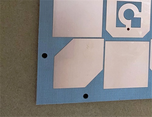
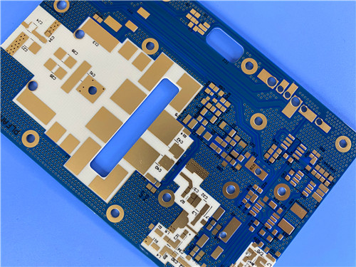
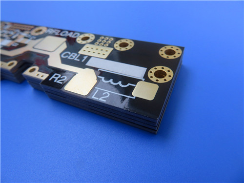
F4BTMS1000 PCB


Head-to-Head Technical Performance Comparison

To provide a fair and accurate assessment, we have compared the F4BTMS1000 with two of the most widely usedhigh-dielectric constant substrates in the aerospace and defense industry. All data presented below is based on independent third-party laboratory testing conducted at 10 GHz and 20 GHz, the frequency ranges most relevant to modern high-frequency applications.


Performance Parameter

F4BTMS1000

Global Competitor A

Global Competitor B

Dielectric Constant (Dk) @ 10GHz

10.2

10

10.3

Dissipation Factor (Df) @ 10GHz

0.002

0.0022

0.0021

Dissipation Factor (Df) @ 20GHz

0.0023

0.0026

0.0025

CTE X-axis (-55°C to 288°C)

16 ppm/°C

18 ppm/°C

17 ppm/°C

CTE Y-axis (-55°C to 288°C)

18 ppm/°C

19 ppm/°C

18 ppm/°C

CTE Z-axis (-55°C to 288°C)

32 ppm/°C

35 ppm/°C

33 ppm/°C

Thermal Conductivity

0.81 W/mK

0.75 W/mK

0.78 W/mK

Moisture Absorption

0.03%

0.04%

0.04%

Thermal Coefficient of Dk

-320 ppm/°C

-350 ppm/°C

-330 ppm/°C

Standard Copper Foil

RTF Low-Roughness

Standard ED

Standard ED


Electrical Performance: Superior Signal Integrity at High Frequencies

At microwave and millimeter-wave frequencies, even small differences in dissipation factor can have a dramatic impact on system performance. The F4BTMS1000 DK10 substrate boasts the lowest dissipation factor among the three materials, measuring just 0.0020 at 10 GHz and 0.0023 at 20 GHz. This translates to approximately 10-12% lower signal loss compared to its competitors, resulting in higher antenna gain, longer communication ranges, and improved power efficiency.


Equally important is the F4BTMS1000's exceptional dielectric constant stability. Its thermal coefficient of Dk of -320 ppm/°C is better than both competitors, ensuring that the resonant frequency of RF components remains consistent across the entire operating temperature range of -55°C to 150°C. This eliminates the need for complex and expensive temperature compensation circuits, simplifying system design and reducing overall costs.


Thermal-Mechanical Performance: Built for Extreme Environments

Aerospace and defense systems operate in some of the harshest environments on Earth—and beyond. The F4BTMS1000's thermal-mechanical properties are specifically engineered to withstand these extreme conditions. Its coefficients of thermal expansion (CTE) in the X, Y, and Z axes are closely matched to those of copper and ceramic components, minimizing thermal stress during soldering and operation. This significantly reduces the risk of solder joint fatigue and delamination, extending the lifespan of electronic assemblies.


The F4BTMS1000 also offers the highest thermal conductivity of the three materials at 0.81 W/mK. This improved heat dissipation capability allows designers to pack components more densely without overheating, further enhancing system miniaturization. Additionally, its extremely low moisture absorption rate of 0.03% ensures reliable performance even in high-humidity environments, a critical advantage for naval and marine applications.


Material Innovation: The Secret Behind F4BTMS1000's Superiority

The F4BTMS1000's exceptional performance stems from its innovative material formulation. Unlike traditional high-dielectric substrates that rely heavily on glass fiber cloth for reinforcement, the F4BTMS1000 uses only a minimal amount of ultra-thin, ultra-fine glass fiber. The majority of the dielectric matrix consists of uniformly distributed special nano-ceramic particles, which deliver the high dielectric constant while minimizing dielectric anisotropy.


This unique formulation results in near-isotropic electrical properties, significantly reducing signal skew and phase distortion—particularly problematic in phase-sensitive applications like phased array radars. Furthermore, the F4BTMS1000 comes standard with reverse-treated foil (RTF) low-roughness copper, which reduces conductor loss by up to 25% at 20 GHz compared to conventional electrodeposited copper used by its competitors.


Manufacturing Feasibility and Quality Assurance

While material performance is critical, it is equally important that the material can be manufactured into high-quality PCBs consistently and cost-effectively. At Bicheng, we have developed specializedproviding processes optimized for theF4BTMS1000 material, ensuring that we can deliver PCBs that meet the most stringent industry standards.


Every F4BTMS1000 PCB supplied at Bicheng undergoes 100% electrical testing, automated optical inspection (AOI), and X-ray inspection to verify quality and reliability. We also offer comprehensive impedance testing and thermal cycling testing to validate performance under extreme operating conditions.


Supply Chain and Cost Advantages

Beyond technical performance, the F4BTMS1000 offers significant supply chain and cost advantages over imported materials. As a domestically produced material, it is readily available with lead times of just 2-3 weeks—compared to 12-16 weeks for imported alternatives. This dramatically reduces project timelines and allows manufacturers to respond more quickly to changing market demands.


In terms of cost, the F4BTMS1000 is typically 20-30% less expensive than comparable imported materials. When combined with shorter lead times and reduced inventory costs, this results in substantial total cost of ownership (TCO) savings for our customers.


Conclusion

The data presented in this article clearly demonstrates that the F4BTMS1000 high frequency PCB matches or exceeds the performance of leading international high-dielectric substrates across every critical metric. Its superior electrical performance, exceptional thermal-mechanical stability, and innovative material formulation make it an ideal choice for demanding aerospace, defense, and high-frequency applications.


At Bicheng, we are proud to be asupplier of F4BTMS1000 PCBs. Our technical expertise, advanced manufacturing capabilities, and unwavering commitment to quality make us the ideal partner for your most challenging high-frequency projects. Whether you are looking to reduce costs, shorten lead times, or improve system performance, the F4BTMS1000 offers a compelling alternative to imported materials.


How Does RO4350B LoPro PCB Solve Conductor Loss Issues in High-Speed Electronics?


As electronic systems push toward millimeter-wave frequencies and data rates exceeding 100 Gbps, conductor loss has emerged as the single most critical bottleneck limiting performance. In 5G mmWave base stations, satellite communication payloads, and high-speed data center backplanes, even a 0.1 dB/inch increase in signal attenuation can translate to 10% shorter coverage range or a doubling of bit error rates. While standard high-frequency materials like conventional Rogers RO4350B represented a major advancement over FR-4, they still struggle with excessive conductor loss at frequencies above 20 GHz. RO4350B LoPro PCB addresses this fundamental limitation through a proprietary copper foil technology that delivers up to 30% lower conductor loss without sacrificing manufacturability or reliability.


The Physics of Conductor Loss: Why Surface Roughness Matters


To understand how RO4350B LoPro solves conductor loss issues, it is first necessary to examine the underlying physical principles. At high frequencies, alternating current does not flow uniformly through the entire cross-section of a copper conductor. Instead, it concentrates in a thin layer near the surface—a phenomenon known as the skin effect. The depth of this layer, called the skin depth, decreases inversely with the square root of frequency.


At 10 GHz, the skin depth in copper is approximately 0.66μm. At 40 GHz, it shrinks to just 0.33μm—less than the thickness of a human hair. This means that at mmWave frequencies, virtually all signal current flows within the top 0.5μm of the copper foil. Consequently, the surface roughness of the copper becomes the dominant factor in determining conductor loss, far outweighing dielectric loss in many applications.


Standard electrodeposited copper foils used in conventional RO4350B laminates have a surface roughness of approximately 2.0μm RMS—more than six times the skin depth at 40 GHz. The irregular peaks and valleys on the foil surface cause signal scattering, reflection, and absorption, significantly increasing attenuation. This roughness also introduces signal phase distortion and is a primary source of passive intermodulation (PIM) in wireless communication systems.


The RO4350B LoPro Breakthrough: Reverse-Treated Foil Technology


RO4350B Low Profile laminates solve the conductor loss problem through a revolutionary bonding process developed by Rogers Corporation. Unlike standard RO4350B, which uses conventional electrodeposited copper foils, RO4350B LoPro incorporates reverse-treated foil (RTF) that is specially engineered to have an extremely smooth surface while maintaining excellent adhesion to the dielectric material.


The proprietary Rogers technology modifies the copper foil surface to achieve a roughness of less than 0.6μm RMS—more than three times smoother than standard copper foils. This dramatic reduction in surface roughness directly translates to lower conductor loss. Independent testing has shown that RO4350B LoPro reduces overall insertion loss by up to 30% compared to standard RO4350B at frequencies above 20 GHz. At 40 GHz, this difference amounts to approximately 0.5 dB/inch—a significant improvement that can make the difference between a working design and one that fails to meet performance specifications.


Crucially, this performance enhancement does not come at the expense of the other desirable properties that have made RO4350B the industry standard for high-frequency applications. RO4350B LoPro maintains the same stable dielectric constant of 3.48±0.05 at 10 GHz and 23°C, with minimal variation across temperature and frequency ranges. It also retains the low dissipation factor of 0.0037 at 10 GHz, ensuring that dielectric loss remains negligible even at extremely high frequencies.


RO4350B LoPro PCB


Beyond Lower Loss: Cascading Performance Benefits


The reduction in conductor loss provided by RO4350B LoPro creates a cascade of additional performance benefits that improve overall system reliability and efficiency.


First, the smoother copper surface significantly reduces passive intermodulation (PIM) levels. PIM is a critical issue in cellular base stations, where it can cause interference between different frequency bands and degrade network performance. RO4350B LoPro's low PIM characteristics make it the material of choice for antenna elements and power amplifiers in 5G and 4G LTE networks.


Second, lower conductor loss means less energy is converted into heat during signal transmission. This improved energy efficiency, combined with RO4350B LoPro's high thermal conductivity of 0.69 W/mK (more than twice that of standard FR-4), helps dissipate heat more effectively, reducing hotspots and extending the lifespan of electronic components. This is particularly important for high-power applications such as base station power amplifiers, where thermal management is a major design challenge.


Third, RO4350B LoPro offers excellent dimensional stability and thermal expansion matching. Its X-axis coefficient of thermal expansion (CTE) is 10 ppm/°C, Y-axis is 12 ppm/°C, and Z-axis is 32 ppm/°C—values that closely match the CTE of copper (approximately 17 ppm/°C). This close matching minimizes thermal stress on plated through-holes, significantly reducing the risk of via cracking and improving long-term reliability, even in applications exposed to extreme temperature variations from -55°C to 288°C.


Manufacturing Advantages That Make High Performance Accessible


One of the most significant advantages of RO4350B LoPro over competing low-loss materials is its compatibility with standard FR-4 manufacturing processes. Unlike PTFE-based materials, which require specialized equipment, sodium etch via preparation, and extended processing times, RO4350B LoPro can be fabricated using the same equipment and processes used for standard epoxy-glass PCBs. This compatibility translates directly to lower manufacturing costs and shorter lead times, making high-frequency performance accessible to a wider range of applications.


At Bicheng PCB, we have extensive experience manufacturing RO4350B LoPro PCBs with tight tolerances and complex designs. Our standard 2-layer RO4350B LoPro PCB measures 78mm x 101mm and features a finished thickness of just 0.2 mm, making it ideal for compact high-frequency modules. We can achieve minimum trace/space of 5/6 mils and minimum hole sizes of 0.25 mm, with 1 oz (35μm) outer copper layers and 20μm via plating thickness for reliable electrical connections.


All our RO4350B LoPro high freqeuncy PCBs are manufactured to IPC-Class-2 standards and undergo 100% electrical testing prior to shipment to guarantee performance. We accept Gerber RS-274-X artwork files, the industry standard for PCB manufacturing, and offer worldwide shipping to customers across North America, Europe, Asia, and beyond. Our standard stackup consists of 35μm copper on both sides with a 4 mil (0.102 mm) thick RO4350B LoPro substrate, providing excellent signal integrity while maintaining mechanical stability.


Conclusion

RO4350B low profile PCB represents a significant advancement in high-frequency PCB technology, providing a comprehensive solution to the conductor loss problem that has long plagued high-speed electronic designs. By reducing copper foil surface roughness by more than 70% while maintaining all the desirable properties of standard RO4350B, it enables reliable operation at frequencies exceeding 40 GHz, improves PIM performance, enhances thermal management, and ensures long-term reliability.


At Bicheng PCB, we combine our expertise in high-frequency PCB manufacturing with the superior performance of RO4350B LoPro to deliver high-quality products that meet the most demanding requirements of the electronics industry. Whether you are designing 5G mmWave base stations, satellite communication systems, or high-speed data center equipment, RO4350B LoPro PCB from Bicheng PCB is the ideal solution for your high-frequency design challenges.


Is F4BTM298 a Practical Premium Laminate Alternative?


Quick Answer


Yes—Wangling F4BTM298 is a practical alternative to imported premium RF laminates for many high-frequency designs, particularly those targeting 10 GHz and below where a Dk of 2.98 fits the application. Manufactured by Wangling using a PTFE nano-ceramic composite with fiberglass reinforcement, it delivers Dk 2.98±0.06 and Df 0.0018 at 10 GHz, matching the loss performance tier of mid-range imported hydrocarbon ceramics while offering shorter lead times and better pricing for Asia-based production. It is not a drop-in replacement for every premium material—Dk values differ, and the highest-frequency PIM-critical designs still benefit from RTF copper variants—but for base station feed networks, power dividers, couplers, and L-to-Ku band passive circuits, F4BTM298 consistently meets specifications and has been proven in volume production at Bicheng.


Key Takeaways

- Comparable loss performance: Df of 0.0018 at 10 GHz places F4BTM298 in the same low-loss category as established premium hydrocarbon ceramic laminates.


- Dk of 2.98 fills a niche between 3.55-class materials (such as RO4003C) and lower-Dk pure PTFE boards, suiting designs originally characterized around the 3.0 Dk range.


- Shorter domestic supply chains reduce lead times from 8–12 weeks for imported specialty materials to standard PCB production cycles for Wangling-based boards.


- Two copper options—ED foil for cost-sensitive designs and RTF foil (F4BTME298) for PIM-critical applications—cover most premium-laminate use cases.


- IPC-Class-2 manufacturability and UL-94 V-0 ensure the material scales from prototype to volume production without qualification surprises.


---


The Case for Domestic Alternatives


  • Engineers designing RF and microwave products have long relied on a small set of imported high-frequency laminates, accepting long lead times and premium pricing because no domestic alternatives met their performance bar. That landscape has shifted. Wangling F4BTM series, and specifically F4BTM298, has emerged as a credible option for engineers looking to second-source materials, reduce BOM cost, or simply escape the supply chain volatility that has plagued imported specialty substrates in recent years.


  • The question is not whether F4BTM298 is identical to every premium laminate on the market—no two material families are. The practical question is whether it performs well enough, reliably enough, and consistently enough to replace an imported material in a given design. The answer depends on frequency band, loss budget, PIM requirements, and thermal environment.


F4BTM298 PCB


F4BTM298 Performance Profile


  • F4BTM298 is built on a PTFE resin matrix reinforced with fiberglass cloth and filled with nano-scale ceramic particles. The nano-ceramic infusion is the key technical differentiator from basic glass-filled PTFE. It raises the dielectric constant to a controlled 2.98, improves thermal conductivity, reduces the coefficient of thermal expansion, and enhances heat resistance—all without sacrificing the low-loss characteristics that make PTFE attractive for high-frequency use.


  • At 10 GHz, the material delivers a dissipation factor of 0.0018. This is an order of magnitude better than FR-4 and competitive with mid-range imported hydrocarbon ceramics. For a typical 50 mm microstrip line at 8 GHz, insertion loss lands in the 0.2–0.3 dB range—low enough that passive components like 3 dB power dividers and directional couplers meet standard link budgets without redesign.


  • The Dk tolerance of±0.06 across the panel is another critical metric. Impedance control depends on predictable dielectric constant, and a 0.06 Dk window on a 0.254 mm substrate translates to roughly±0.5 ohm variation on a nominal 50-ohm line—well within the±10% impedance tolerance that most RF systems specify. For phase-sensitive designs such as phased array elements, this uniformity means consistent electrical length across boards from different production batches.


Head-to-Head with Imported Premium Laminates


  • Direct comparison requires care because no two materials share identical specifications. F4BTM298 sits in a specific Dk band of 2.98, which is lower than the widely used RO4003C family(Dk 3.55) and closer to pure PTFE materials. This means a design originally laid out for 3.55 Dk cannot be dropped in without adjusting trace widths for impedance. But for designs targeting a ~3.0 Dk substrate—or for new projects where the engineer has flexibility in material selection—F4BTM298 is a strong candidate.


  • On loss performance, F4BTM298's Df of 0.0018 at 10 GHz is competitive with mid-tier imported ceramics. It will not match the absolute lowest-loss specialty PTFE materials used at millimeter-wave frequencies, but those carry price tags several times higher and are overkill for most applications below 15 GHz.


  • Thermally, F4BTM298 holds up well. Its TCDk of -78 ppm/°C means less than 1.6% Dk drift across a 200°C range. Some imported materials offer slightly better TCDk figures (in the -40 to -50 ppm/°C range), but the difference is meaningful only in the most temperature-critical designs—typically high-precision phase shifters or millimeter-wave systems with extremely tight phase budgets. For the vast majority of base station, satellite ground, and radar subsystems, -78 ppm/°C is more than adequate and requires no active temperature compensation.


Supply Chain and Manufacturing Practicality


  • The practical advantages of F4BTM298 extend beyond raw electrical specs. Because Wangling is a domestic Chinese manufacturer, lead times for raw laminate are measured in days and weeks, not months. Imported premium laminates often carry 8–12 week lead times for non-stock thicknesses, and even standard gauges can see delays during periods of high demand. For OEMs running production in China or Southeast Asia, sourcing F4BTM298 locally eliminates customs clearance, international freight delays, and currency fluctuation risk.


  • Manufacturability is another practical consideration. F4BTM298 processes on standard PCB equipment with well-understood parameters. Drilling, plating, etching, and lamination all follow established PTFE processing guidelines that PCB fabricators like Bicheng have refined over years of production. The material achieves IPC-Class-2 acceptance criteria consistently, with 20μm minimum via plating thickness and 100% electrical test coverage on every shipment. This is not a laboratory material requiring special process development—it is a production-ready substrate.


Design Migration Considerations


  • Engineers considering a switch from an imported premium laminate to F4BTM298 should account for three factors. First, Dk difference: if the original design was simulated at 3.55 Dk, trace widths for controlled-impedance lines must be recalculated for 2.98 Dk. On a 0.254 mm substrate, a 50-ohm microstrip line narrows from roughly 0.51 mm at 3.55 Dk to about 0.73 mm at 2.98 Dk—a noticeable change that requires layout adjustment.


  • Second, copper foil type: if the original design uses rolled-annealed copper for ultra-low PIM, standard F4BTM298 with ED copper may not be sufficient. In that case, specify F4BTME298 with reverse-treated (RTF) copper, which delivers excellent PIM performance and lower conductor loss at high frequencies.


  • Third, mechanical stackup: F4BTM298 is available in the 0.254 mm (10 mil) core thickness as standard, with other thicknesses available on request. Verify that the desired finished board thickness is a stocked item to avoid custom laminate lead times.


---


Real-World Migration Case


A Bicheng customer manufacturing L-band base station feed networks provides a concrete example. The customer's original design used an imported PTFE-based laminate and was fully qualified. When a supply disruption extended lead times to 11 weeks, the customer needed a drop-in alternative to keep production running.


Because the original material had a Dk close to 3.0, the impedance change was minimal—less than 1 ohm on the 50-ohm lines—and well within the system's return loss margin. Bicheng built first-article boards on F4BTM298 and ran full S-parameter characterization. Across the 0.8–2.2 GHz operating band, insertion loss matched the original material within 0.05 dB, return loss exceeded -22 dB on all ports, and phase balance between outputs stayed under 1.5 degrees, compared to a 3-degree specification.


The customer qualified F4BTM298 as a second source within two weeks and has since shifted a significant portion of production volume to the material. The primary benefit was not a dramatic performance improvement—the material performs comparably—but supply chain resilience and a meaningful reduction in per-board material cost, with no compromise in electrical specifications.


---


Comparative Specification Reference


F4BTM298 Comparative Specification Reference


Frequently Asked Questions


1) Q: Can F4BTM298 directly replace Rogers RO4003C without redesign?


Not without layout adjustment, because the Dk values differ—2.98 versus 3.55. Controlled-impedance traces must be resized to maintain the same target impedance, which means updating the Gerber files. However, the overall design topology, component placement, and system architecture remain valid. For new designs starting from scratch, or for projects where a layout revision is already planned, migrating to F4BTM298 is straightforward and can yield meaningful cost and lead-time savings.


2) Q: Is F4BTM298 suitable for millimeter-wave designs above 20 GHz?


F4BTM298 is primarily characterized at 10 GHz and performs reliably well into the Ku band (12–18 GHz). Above 20 GHz, conductor losses begin to dominate, and the surface roughness of standard ED copper becomes a limiting factor. For Ka-band and higher millimeter-wave applications, we recommend evaluating the F4BTME298 variant with RTF copper foil, which has a smoother surface profile that reduces skin-effect loss. The very highest mmWave designs may still require ultra-smooth rolled copper laminates, but F4BTME298 covers a substantial middle ground.


3) Q: How does the cost compare to imported premium laminates?


F4BTM298 typically offers 25–40% raw material cost savings compared to equivalent imported hydrocarbon ceramic laminates, with the exact delta depending on thickness, copper weight, and volume. The savings are amplified when factoring in shorter lead times, no import duties or international freight for Asia-based production, and reduced inventory carrying costs. For volume production runs, the accumulated savings can be substantial enough to fund the initial design migration and qualification effort.


4) Q: What quality certifications does F4BTM298 carry?


F4BTM298 laminates carry UL-94 V-0 flammability certification and are manufactured under Wangling's ISO-certified production processes. PCBs built on F4BTM298 at Bicheng are fabricated to IPC-Class-2 acceptance criteria as standard, with IPC-Class-3 available on request. Every production lot undergoes standard material inspection, and every finished PCB receives 100% electrical testing before shipment. For customers requiring formal material qualification, Bicheng can provide test coupons and supporting documentation.


5) Q: Are multi-layer boards possible with F4BTM298?


Yes. While the reference design discussed here is a 2-layer 0.3 mm board, F4BTM298 is available in multiple core thicknesses and can be used in multi-layer stackups with compatible prepreg. Hybrid stackups combining F4BTM298 in RF sections with FR-4 or low-loss epoxy in digital sections are also common and cost-effective for mixed-signal designs. Bicheng supports 4-layer, 6-layer, and custom multi-layer configurations on F4BTM298, with controlled impedance across all signal layers.


---

Conclusion


F4BTM298 high frequency PCBs aresupplied by Bicheng, an authorized OEM partner of Wangling High-Frequency Materials, and are available for worldwide shipment. All boards receive 100% electrical testing and meet IPC-Class-2 acceptance standards. For second-source evaluation or design migration support, contact Bicheng's technical team with your Gerber files and material requirements.